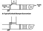
FIGURE 1. Comparison between a typical linked damper economizer and a typical unlinked damper economizer.
Until recently, the HVAC industry relied on control solutions with a demonstrated tradition of success. Now, however, with new technologies at their disposal, engineers are experimenting with control solutions unlike those that worked in the past. For example, in an ES magazine article titled, "Operating Chillers In The Max-Cap Range" (June 2003, page 66), Gil Avery questioned the design and control of central chilled water systems, particularly variable-flow systems.
This article examines control solutions that break from traditional methods of controlling economizers, air filtration, mixing, and ventilation. Each solution requires engineers to think outside the box, as it takes a simple approach to a common challenge and offers the potential for significant reductions in energy usage.

FIGURE 2. Parallel-blade dampers for both the outdoor and return air, when modulated in equal increments but opposite directions from 100% return air to 100% outdoor air, provide the most consistent system pressure drop at all positions of the two dampers, in draw-through, single-fan applications.
A BETTER WAY OF CONTROLLING ECONOMIZERS
VAV air-handling systems are equipped with routine configurations and control applications that are regularly taken for granted. For example, a single damper actuator often mechanically links and controls the outdoor and return air dampers of an airside economizer. Even if multiple actuators are used, they are often connected to the same output from an electronic controller (Figure 1), and still work in tandem. Furthermore, when multiple actuators are controlled from different outputs, the control sequence is generally written so the outdoor air damper opens while the return damper closes at an equal rate. These control methods are traditional, proven, and comfortable, but they do not necessarily represent the best way of controlling economizer systems.Fifty years ago, almost all HVAC systems were constant-volume and variable-temperature systems. Fan sheaves needed to be adjusted and balancing dampers set so that the constant-speed fan could maintain a constant volume of air flowing at all times. Any variation in system resistance affected the amount of airflow in the system.
Many papers were written and research was conducted to determine the best way of sizing and selecting damper characteristics so the pressure drop in the mixing-box section of the AHU remained constant as the system went from minimum outdoor air to 100% outdoor air.
ASHRAE research1determined that in a simple, draw-through, single-fan application, parallel-blade dampers for both the outdoor and return air, when modulated in equal increments but in opposite directions from 100% return air to 100% outdoor air, provided the most consistent system pressure drop at all positions of the two dampers (Figure 2).
Opposed-blade dampers exhibited almost four times the pressure drop with both dampers throttled 50% vs. one damper open 100% and the other damper closed (Figure 3). Researchers concluded that parallel-blade outdoor and return air dampers, modulated together, provide the most linear response for constant-flow systems. Note that this example is for HVAC systems with no return fan and almost equal pressure drop in the outdoor and return air paths.
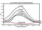
FIGURE 3. Opposed-blade dampers exhibited almost four times the pressure drop with both dampers throttled 50% vs. one damper open 100% and the other damper closed.
OPPOSED BLADES FOR BETTER MIXING AND EFFICIENCY IN VAV
A recent ASHRAE research project, RP-1045, pointed out that parallel-blade dampers, arranged to direct the airflows into each other as shown in Figure 1, do not effectively mix the air. The two airstreams can pass through each other, remain stratified, and exchange very little heat. Consideration should be given to using opposed-blade dampers to enhance the mixing of air in mixing boxes, provided the dampers are sequenced and not modulated simultaneously. Additional research is needed on how much better opposed-blade dampers mix the air, since RP-1045 only addressed parallel-blade dampers throttled simultaneously in the traditional manner.VAV systems operate more efficiently than their constant-volume counterparts in part because they are not constrained by the constant pressure requirement of constant volume systems. If, for example, both the outdoor air damper and the return air damper in a VAV system were opened 100% to get a 50/50 mix of outdoor air and return air, the pressure drop through the dampers would be reduced by 84%, compared to the pressure drop using the conventional control common to a constant-volume system, as calculated below.
Opening both dampers 100% in a constant volume system would cause an undesirable increase in airflow.
Formula: CFM1/CFM2= (ΔP1/ΔP2) 0.5
If the pressure drop at full airflow and 1,100 fpm face velocity through a wide open damper was 0.24 in. w.g., the pressure drop at 50% airflow through the same wide open damper would be:
CFM1/0.5CFM1= (0.24/ΔP2)0.5
ΔP2= 0.06 in. w.g.
From Figure 2, this compares to a pressure drop of 0.38 in. if the damper was throttled 50%. Thus, at 50% airflow, the mixing box static pressure reduction is 0.38 - 0.06 = 0.32 in., or 84%.
If the fan system were operating at 4 in. total static pressure (sp), this 0.32 in w.g. savings for sequenced dampers would equate to approximately 12% savings in fan hp.
BHP2/BHP1= [(SP2/SP1)0.5]3
BHP2/BHP1= [(3.68/4.0)0.5]3= 0.88
Taking the example one step further, if the dampers were opposed blade, opening both dampers 100% would result in a reduction of more than 90% of the mixing-box pressure drop compared to the pressure if the dampers were equally throttled dampers.
If the system had opposed-blade dampers, the reduction in fan hp would be significantly higher. For example, in Figure 3, if the wide-open inlet velocity through one damper was 1,100 fpm, the wide-open pressure drop would be approximately 0.35 in. w.g., but the 50% throttled pressure drop would be approximately 1.75 in. w.g. If both dampers were opened 100%, the velocity through each damper would be 550 fpm and the pressure drop would be 0.10 in. w.g. This results in a savings of 1.65 in. w.g., or 94%.
Again, with 4 in. total sp on the fan system, the required fan hp drops to 45% percent during the time the system is in the 50% mixing mode. The red lines on Figures 2 and 3 indicate the mixing box pressure drop achieved in a VAV system by sequencing the dampers open to control air volumes rather than sequencing them closed.
To open both dampers 100% when equal parts of outdoor air and return air are required is not a complex control algorithm. It merely requires sequencing the dampers. The suggested sequence of operation follows:
"The fan(s) shall start with the return air damper fully open and the outdoor air damper closed. After the fan is started, the outdoor air damper will open to its minimum position, and the return damper shall remain fully open. The outdoor air damper shall modulate further open to admit additional outdoor air as required to satisfy the (mixed air), (discharge air) temperature sensor or IAQ requirements. After the outdoor air damper is fully open, if additional outdoor air is required, the return air damper shall modulate toward its closed position."
In its simplest form, this could be accomplished by driving the outdoor air damper and the return damper actuators with the same control signal but setting the driving span of the outdoor-air damper actuator at 3 to 6 V and the return actuator at 6 to 9 V. However, the typical approach would be to drive the two actuators from independent, but sequenced outputs.
Generally, stability of the mixing damper control loop is not a problem. However, this sequence also adds stability, because only one actuator is driving at one time.
The above sequence can be used to save fan energy, regardless of the type of dampers or fan system configuration. That is, the damper sequence can be utilized with systems with or without exhaust fans or return exhaust fans.
Savings with this sequence are not limited to the 50% outside air condition either. Any time less than 100% outside air or 100% return air is being used, the fan hp is reduced, as illustrated by the reduced mixing box pressure drop throughout the operating range, which is indicated by the red lines in Figures 2 and 3. Although the percentages are not terribly high, the number of hours during which savings occur will often be significant. These savings are the result of a simple change in the traditional control sequence.
The above sequence assumes relatively equal pressure drop through the outdoor air and return air paths. For situations with grossly oversized outdoor air dampers and restricted return paths, which are not uncommon if outdoor air dampers are louver-sized, additional corrective action is required.
Oversized outdoor air dampers and restricted return paths, with or without power-exhaust fans, present problems for traditional economizer control as well. The best corrective action is to add restriction to the outdoor path and reduce the restriction in the return path, so that the pressure drop through both paths is relatively equal at design flow.
In addition, grossly oversized outdoor air dampers and restricted returns can lead to the power-exhaust fan drawing outdoor air instead of return air when the supply fan is operating at a high percentage of outdoor air. A previous article on this subject2suggests that if the system has high return pressure loss and a high percentage of outdoor air, a return fan is warranted.
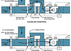
FIGURE 4. Face-and-bypass dampers around the filters, with a bypass sufficiently large to keep the pressure drop to a minimum, can be used when outdoor air only needs gas-phase or HEPA filtration a few days a month.
DEMAND-CONTROLLED FILTRATION
The above sequence makes reference to opening the outdoor air damper as necessary to meet IAQ requirements. However, is bringing in more outdoor air the best solution to IAQ problems? If the IAQ problem is due to humidity or buildup of volatile organic compounds (VOCs), bringing in more outdoor air may exacerbate the problem, particularly if the VOC contaminant is from the outdoor air. If such is the case, the best response is to introduce the amount of outdoor air required to meet minimum ventilation air codes, or additional air to meet full-occupancy requirements and to add gas-phase and HEPA filtration for the VOC and particulate contaminants.But what if the outdoor air only needs gas-phase or HEPA filtration a few days a month? This may be the case when an industrial plant is upwind and emitting offensive odors, or an ozone alert has been declared. Obviously, it is not practical to install gas-phase filters only on those days. But on the days filters are not required, they create unnecessary pressure drop in the system. How about a non-traditional solution? Providing face-and-bypass dampers around the filters, with a bypass sufficiently large to keep the pressure drop to a minimum, provides a non-traditional solution to the problem (Figure 4).
Control does not have to be complicated. It can be as simple as flipping a switch on days when an ozone alert has been issued. It could also be automated with a sensor that monitors the pollutant of concern, or with one of the broadband silver-oxide IAQ sensors tuned to the air quality at the site. If the pollutant is in the return, it is generally more cost-effective to filter the pollutant out rather than dilute it with outdoor air, if the outdoor air requires additional heating or cooling energy to meet thermal requirements.
Again, a face-and-bypass damper arrangement may save fan hp and extend filter life, if the requirement for gas-phase filtration is intermittent. Note: if a face-and-bypass arrangement is used with HEPA filtration, extreme care must be taken to eliminate leakage through the bypass damper when the system is in the filtration mode. In a 20,000 cfm AHU, a leak as small as 4 cfm (0.02%) is sufficient to compromise the integrity of the HEPA filtration system; therefore using a typical "low leakage" damper (4 cfm/sq ft at 1 in. w.g.) for the bypass may not be sufficient.

FIGURE 5. Properly distributing air throughout the building envelope is key to reducing energy costs. One solution can be to activate the fan in a parallel-fan box that serves the room when a CO2 sensor in the space indicates that an under-ventilated condition exists.
DEMAND-CONTROLLED VENTILATION
CO2sensors can be used in a variety of ways to bring more ventilation air into a building or room when the CO2level rises either above a fixed setpoint or above a maximum differential over the outdoor CO2level. With a typical VAV system that serves a conference room or other room with widely varying occupancy, the typical approach is to set a minimum airflow setpoint for average or minimal occupancy and override the minimum setpoint as the CO2level increases. This increase in airflow over requirements of the thermostat usually requires reheat to compensate for more supply air than is necessary to satisfy the thermostat.Another often-used alternative increases the amount of outdoor air being introduced at the AHU and also increases energy costs by requiring heating/cooling/filtering of this air. In both cases, extra people in the conference room often come from adjoining offices, resulting in over-ventilation of those unoccupied spaces. There is probably enough outdoor air in the building. The challenge is to properly distribute that air throughout the envelope. The solution to the challenge may be as simple as activating the fan in a parallel-fan box that serves the room when a CO2sensor in the space indicates that an under-ventilated condition exists (Figure 5). The parallel fan acts as a transfer fan, moving additional unvitiated air into the overpopulated space. If adding the transfer air does not reduce the CO2level in the space, the minimum primary airflow to the space can be increased.
A CO2sensor in the return air of the AHU will indicate if sufficient outdoor air is being introduced into the building. If the sensor in the return air indicates high CO2levels, increasing the amount of air brought in by the AHU is the solution. However, before introducing more primary air to a given space, the first step should be to introduce transfer air from less occupied areas into the space, because this air has already been heated/cooled/filtered, and can be used for dilution of contaminants with a minimal energy penalty.
