Ventilation air distribution in all-air variable-air volume (vav) systems. Engineers cannot be sure where the ventilation air, in all-air systems, is distributed once brought into the building and mixed with return air at the air-handling unit (ahu). Proper distribution is a function of vav box minimum settings, space sensible loads, local exhaust and exfiltration, short circuiting paths, and interzonal air transfer (Mumma, Lee 1998). Complete knowledge of all of these factors at design is not possible, much less in real time. Therefore engineers cannot really defend compliance with ASHRAE Standard 62-1999 (ASHRAE 1999) when using all-air vav systems. On the contrary, dedicated 100% OA systems place the proper ventilation air quantities into every space.
Excess OA flow and conditioning required for all-air vav systems. When the multiple spaces equation of ASHRAE Standard 62-1999 is used, generally from 20% to 70% more outdoor air is required in an effort to ensure proper ventilation air distribution in all-air systems than is required with a dedicated outdoor air system. Cooling and dehumidifying the high OA quantities in the summer and humidifying and heating the air in the winter is an energy-intensive proposition.
Vav box minimum settings must be surprisingly high. Perhaps contrary to current practice, vav box minimums must reflect both the ventilation requirements of the space and the fraction of ventilation air in the supply air. For example, a space requiring 200 scfm (ft3/min at standard temperature and pressure) of ventilation air and served with supply air that is 40% ventilation air, will require a box minimum setting of 500 scfm (i.e., 200/0.4) rather than the conventional practice of 200 scfm. When the box minimums are properly set to satisfy the ventilation requirements, the potential for considerable terminal reheat becomes an issue. Therefore, properly operating all-air vav systems will always use more terminal reheat than dedicated outdoor air systems supplying air at the same temperature (typically 55°F).
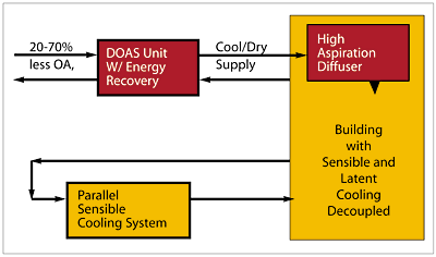
The inability of most all-air vav systems as currently designed to decouple the space sensible and latent loads. The inability to decouple the space sensible and latent loads leads to high space relative humidity at low sensible loads in the occupied spaces. Properly designed dedicated OA systems can accommodate 100% of the space latent loads and a portion of the space sensible loads, thus decoupling the space sensible and latent loads. A parallel, sensible-only cooling system, as illustrated in Figure 1, is then used to accommodate the sensible loads not met by the dedicated OA systems.
When all of the OA load, all of the space latent load, and up to 30% of the space sensible load is accommodated by the dedicated OA system, only about 40% of the design chiller load must be borne by the parallel sensible-only cooling system. There is therefore a strong incentive to control the space latent loads independently of the space sensible loads to avoid moisture-related IAQ problems.
The Terminal Reheat And Excess OA Issues
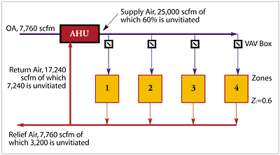
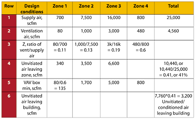
The first problem identified above, proper ventilation air distribution, has caused the industry, through ASHRAE Standard 62, to develop the multiple spaces approach in an attempt to deliver sufficient ventilation air to all occupants. In virtually all cases, the ventilation air required for a building is greater than that obtained by the product of occupants times the required ventilation of 15 or 20 scfm per occupant. Excess ventilation air is the second major issue identified above. These two issues, along with the third issue of vav box minimum settings, are best illustrated with an example.Consider the all-air vav four-zone system illustrated in Figure 2 along with the data presented in Table 1. In this example, it is assumed that the design supply airflow rates range from 700 csfm for zone 1 to 16,000 scfm for zone 3. The total design airflow rate to the building in this example is 25,000 scfm. Similarly, the ventilation air required (row 2) for each zone ranges from 80 scfm for zone 1 to 3,000 scfm for zone 3. The total uncorrected OA flow rate is then 4,560 scfm. The ratio of ventilation air to supply air, Z, is presented in the third row of data. The ratio ranges from 0.11 to 0.6.
At this point, it is important to realize that the critical Z (largest number), zone 4 in this example, dictates the fraction of ventilation air that must be in the supply air leaving the ahu (i.e., 0.6 • 25,000 = 15,000 scfm). Clearly zones 1 to 3 are overventilated, as illustrated by row 4 of the table. The total overventilated air, or unvitiated air, in the relief air plenum is 10,440 scfm. In other words, the return air at this point is 10,440÷25,000 or 41% unvitiated air. That means that the relief air is 41% unvitiated air.
Applying the multiple spaces equation of ASHRAE Standard. 62 [Y = x÷(1+x-Zc)], to this example:
x = 4,560÷25,000 = 0.18, and is the ratio of uncorrected OA to supply airflow rates,
Zc = 0.6. So Y = 0.18÷(1+0.18-0.6) = 0.31, and is the fraction of ventilation air in the total supply air that must be brought into the building directly from outside (note, Y is less than Zc but more than x as is almost universally true since the recirculated air has unvitiated air in it).
Therefore, the required new OA directly from outside in this example is:
OA = Y • 25,000 = 7,760 scfm
By comparison, a dedicated OA system would need to bring in and condition only 4,560 scfm, or 3,200 scfm less. The required overventilation for all-air vav systems is an expensive operating cost penalty compared to dedicated OA systems. Row 6 of the table illustrates that indeed 3,200 scfm of unvitiated air is exhausted with the relief air.
Finally, the issue of vav box minimum settings for proper ventilation will be discussed. This is illustrated in row 5 of the table. Since Zc=0.6, or 60% of the supply air is unvitiated air, the box minimums are computed by dividing the minimum ventilation air by Zc. Each of the box minimum settings is much higher than is used in most current practice.
Further, note that the box minimum setting in the critical zone is at the design supply making that zone a constant-volume zone. Clearly each of these zones would require more terminal reheat to avoid overcooling than would be the case when much smaller dedicated OA supply airflow rates are used. In this example, Zc=0.6 was used, but this is higher than most design engineers will tolerate. When Zc is reduced by any number of methods, the box minimums increase further. Clearly, in all-air vav systems there must be some tradeoff between reducing the energy required to condition OA and the associated increase in fan energy and terminal reheat with higher vav box minimums.
Decoupling The Building Latent And Sensible Loads Using 100% OA Systems
In order to decouple the space latent and sensible loads using the small volumetric flow rates of OA (approximately 20% of the normal vav design flow), the supply air dewpoint temperature must be suppressed more than is typical with an all-air vav system. If the bulk of the latent load is from the occupants (approximately 205 Btuh/person), and each occupant receives 20 scfm of OA, then the change in humidity ratio is approximately 15 grains/lb mDA. Clearly, the supply air dewpoint must be at least 15 grains/lb mDA less that the space target humidity ratio.This approach to meeting all of the space latent loads requires that the building envelope be tight and in conformity to ASHRAE Standard 90.1-1999 (ASHRAE 1999). Large and unpredictable variations in the envelope transmission of moisture, either through infiltration or movable sash, will lead to a loss of space design conditions. Such a loss of control could result in unwanted condensation at the distributed parallel sensible cooling equipment and an associated distributed microbial problem.
The dedicated OA must be cooled and dehumidified in the summer, and humidified and heated or cooled at other times of the year. In the simplest form, the preconditioning could be achieved with a preheating coil, a cooling coil, a reheating coil, and a humidifier. However ASHRAE Standard 90-1999 in section 6.3.6.1 Exhaust Air Energy Recovery requires the following: "Individual fan systems that have both a design supply air capacity of 5000 scfm or greater and have a minimum outside air supply of 70% or greater of the design supply air quantity shall have an energy recovery system with at least 50% recovery effectiveness. Fifty percent energy recovery effectiveness shall mean a change in the enthalpy of the outdoor air supply equal to 50% of the difference between the outdoor air and return air at design conditions."
Consequently, since dedicated OA systems are by definition 100% OA systems, energy recovery is required to supplement the simplest form of preconditioning equipment mentioned above.
Further, ASHRAE Standard 90.1-1999 places the following limitations on reheating (defined in the standard as: "raising the temperature of air that has been previously cooled either by mechanical refrigeration or an economizer system") as it relates to preconditioning the OA. Section 6.3.2.3 Dehumidification says, "Where humidistatic controls are provided, such controls shall prevent reheating, mixing of hot and cold airstreams, or other means of simultaneous heating and cooling of the same airstream."
Exceptions to 6.3.2.3: (e) "At least 75% of the energy for reheating or for providing warm air in mixing systems is provided from a site-recovered energy source."
The ASHRAE Standard 90.1-1999 requirements clearly mandate that a total energy recovery device, such as an enthalpy wheel (EW), also known as a passive desiccant wheel, be used to reduce the load on the cooling coil. In addition, if the supply air is to be delivered at a temperature above the required supply air dewpoint temperature, a sensible energy recovery device is required. While many combinations of the above equipment are possible, the author favors the arrangement illustrated in Figure 3, to be discussed in the following section.
General Configuration Of The Dedicated Outdoor Air System
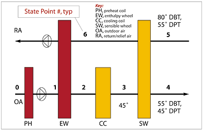
A general layout of the dedicated outdoor air system (DOAS), consisting of a preheat coil, an EW, a deep cooling coil (CC), a sensible heat exchanger, and the prime movers is illustrated in Figure 3. From this point on, the acronym DOAS will mean the set of equipment specified above (Mumma, Shank 2001), even though many other configurations of dedicated OA systems can be conceived. In the configuration illustrated, the sensible heat exchanger is a sensible heat wheel.For the sake of the discussion in this article, this will be the assumed arrangement, although equally good heat exchangers in the form of plate-type or heat pipe are used in the industry. As will be discussed later, the effectiveness of the sensible heat exchanger must be variable down to zero. Modulating its rotational speed alters the effectiveness of the sensible wheel. Heat pipe heat exchangers have some control of effectiveness by altering the unit tilt, but it is not possible to reduce it to zero in this manner.
Plate-type and heatpipe heat exchanger effectiveness must essentially be controlled by the flow rate of one of its air circuits. That means these latter two heat exchangers require face and bypass dampers to limit effectiveness, an alternative that will not be developed further in this article.
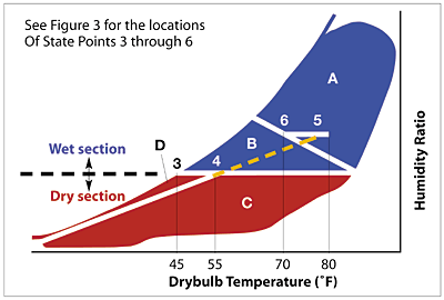
A discussion of the rationale for each of the components in the system and their performance characteristics will be presented next in conjunction with Figures 3 and 4. The blue region of the psychrometric chart depicted in Figure 4 represents the OA conditions that the DOAS unit will encounter during the year (the region shape and density changes some with geographic location). The blue region is broken up into two major sections, one referred to as the wet section when dehumidification is required, and the dry section where humidification is required. The wet section is further subdivided into areas labeled A and B. Likewise, the dry section is further subdivided into areas labeled C and D. Performance of the DOAS equipment in each of these regions will be discussed next.
The Enthalpy Wheel
The enthalpy wheel (also called a passive desiccant or total energy wheel) recovers both sensible (temperature) and latent (moisture) energy. The wheel's desiccant loaded honeycomb rotor design (its appearance is like the edge of a cardboard box) provides for high heat transfer, with low-pressure-loss parameters. Psychrometrically, state 2 is on a straight line connecting states 1 and 6. An 85%-effective EW at design rotational speed will put state 2 very close to state 6 (i.e., within 15% of the distance between states 1 and 6).The benefits of this level of total energy recovery are very strong in the summer, subsection A of Figure 4, in terms of load and energy consumption reduction. It is equally beneficial for minimizing heating, subsection D of Figure 4 and humidification, subsection C and D of Figure 4, energy use during the cold winter months.
A critical word of caution concerning the winter operating conditions: If the straight line joining states 1 and 6 crosses the saturation curve, condensation will occur in the wheel. If the temperature of state 1 is below freezing, then the condensate may freeze in the wheel. In order to avoid this unacceptable condition, preheat is required under certain conditions to prevent frosting of the EW.
Preheat Coil
As noted above, a small preheat coil is required in many locations when the EW is used in the winter. With a proper preheat setpoint reset control schedule (Mumma 2001), only minor preheat energy will be required to avoid freezing, and further heating of the outdoor air is virtually eliminated with the enthalpy wheel.Deep Cooling Coil
For the applications addressed in this article, relatively low DPT [42° to 48°F (6° to 9°C)] air is required in order to remove the entire latent load from the space with the ventilation air and still maintain a target space dewpoint temperature (DPT) in the neighborhood of 50° to 55° (10° to 13°C). During periods of outdoor air DPTs in excess of that required for supply (the wet section of Figure 4), the CC must be controlled to maintain the low DPT. However, when the outdoor air DPTs are below that required by the supply air (the dry section of Figure 4), the control setpoint may be reset up to the desired supply air temperature. In this case, the CC is no longer needed to perform dehumidification.
Sensible Wheel
If the space sensible loads were always sufficiently high to permit the cold air leaving the CC to directly enter the space without local reheat, the sensible wheel would not be desirable or necessary. However, in some applications, the internal and envelope sensible cooling loads may not be sufficiently high to prevent overcooling with the low temperature ventilation air. Therefore, it may be desirable to elevate the supply air temperature. For the sake of this article, it will be assumed that the supply air temperature is elevated to 55° (13°C). The sensible wheel will accomplish this although, as mentioned earlier, other forms of sensible heat transfer equipment could be utilized.
When two equal flow rate air streams exchange energy in the sensible wheel, virtually no moisture is exchanged. For the sensible wheel illustrated in Figure 3, the 45° (7°C) air leaving the deep CC is reheated sensibly (path 3-4 in Figure 4) to 55° (13°C) with energy extracted from the return air stream (path 5-6 in Figure 4). The return air is sensibly cooled by 10° (6°C) in this process, thus lowering the energy content of the return air stream, reducing further the enthalpy of the outdoor air leaving the enthalpy wheel and entering the deep CC.
Supply and Return Fans
These fans must be selected to overcome the resistance to flow from the wheels, coils, and duct systems that they serve. And in some manufacturers' equipment they must also be able to handle the excess air in the purge cycles (when utilized to flush the return air from the wheel before it enters the clean supply air) of the EW. These fans would be required at all times the building is occupied.Filtration
Filters are not shown in Figure 3, since the emphasis is the thermodynamic performance of the system. However at least coarse filtration will be required upstream of the equipment in both the OA and relief air streams.Economizer
A frequent question related to dedicated OA systems is the use of the economizer cycle. ASHRAE Standard 90.1-1999 generally (there are exceptions) requires the use of either an airside or a waterside economizer, unless it can be shown that there is no reduction in energy utilization when employed. An airside economizer is only possible with dedicated OA systems when the parallel sensible-only system is an all-air system. For other distributed parallel system technologies to be introduced later, water-side economizer is required.
The following exception to the operation of a water-side economizer taken from Standard 90.1-1999 will be required for the DOAS when in the dehumidification mode: Exception to 6.3.1.2.1: "Systems in which a water economizer is used and where dehumidification requirements cannot be met using outside air temperatures of 50° dry bulb/45° wetbulb must satisfy 100% of the expected system cooling load at 45° drybulb/40° wetbulb."
Parallel Building Sensible Cooling Choices
As a general observation, the ventilation air may be supplied with temperatures ranging from 75° to 45°F (24° to 7°C). In this range of supply temperatures, for typical ventilation airflow rates, from 0% to 30% of the space sensible loads can be accommodated by the OA. The balance of the space sensible loads must be accommodated with many optional equipment choices. Those choices include:
- A parallel all-air vav system;
- Packaged unitary water-source heat pumps;
- Fan coil units;
- Packaged unitary equipment; and
- Radiant ceiling panels.
It is the author's opinion that radiant ceiling cooling panels (Conroy, Mumma 2001) are the best parallel system for use with the DOAS, and he hopes to make that case in a future article. The small ventilation air ductwork and parallel radiant cooling panel terminal equipment offer a significant opportunity to reduce the required floor-to-floor dimension.
Conclusions
The new paradigm shift in the design of building comfort control systems is in its early stages. The author has written this paper to help facilitate an understanding of what is believed to be the wave of the future. The requirements of the new paradigm include:
- Separating the OA system from the space conditioning systems through the use of a DOAS to ensure proper ventilation air delivery into all occupied spaces.
- Use the DOAS to handle all of the outdoor air load, all of the space latent load and as much of the space sensible load as possible.
- Maximize the cost effective use of energy recovery equipment, thereby complying with ASHRAE Standard 90.1-1999.
- Employing radiant ceiling sensible cooling as the parallel system of choice for occupant sensible thermal control.
In the author's opinion, as more and more dedicated OA design systems are placed in service - which provide superior results in environmental control, IAQ, and cost performance - the dedicated outdoor air paradigm will expand rapidly. ES
Cited Works
Mumma, S. A., B. W. Lee. "Extension Of The Multiple Spaces Concept Of ASHRAE Standard 62 To Include Infiltration, Exhaust/Exfiltration, Interzonal Transfer, And Additional Short Circuit Paths." ASHRAE Transactions V 104(2) 1989: pp. 1232-1241.ASHRAE. ANSI/ASHRAE 62-1999, "Ventilation for Acceptable Indoor Air Quality" ASHRAE 1999.
ASHRAE. ANSI/ASHRAE 90.1-1999, "Energy Efficient Design of New Buildings Except Low-Rise Residential Buildings" ASHRAE 1999.
Mumma, S. A., K. Shank. "Achieving Dry Outside Air in an Energy Efficient Manner." ASHRAE Transactions vol 107(1) 2001.
Mumma, S. A. "Dedicated Outdoor Air-Dual Wheel System Control Requirements." ASHRAE Transactions vol 107(1) 2001.
Conroy, C. L., S. A. Mumma. "Radiant Cooling as a Viable Distributed Sensible Cooling System." ASHRAE Transactions vol 107(1) 2001.
