Higher education institutions use hydronic heating-cooling systems for a broad range of applications. The college hydronic inventory holds more complexity than almost any other class of buildings.
A typical university campus will use hydronic systems to control the environments in offices, classrooms, restaurants, gymnasiums, swimming pools, stadiums, laboratories, cleanrooms, and dormitories. A large campus may well have as many different hydronic systems as a small city.
As demands on the conditioned indoor environment have increased, so has the complexity of these systems. Not only has the number of circulating loops per building increased, but components also are now expected to perform in new applications such as cleanrooms, containment spaces, variable-flow situations, and heat recovery systems.
These are applications without a long history of experimentation and field application. This forces the design community to continue to expand horizons in hydronic design.
New hydronic applications and an increasing number of applications mean more problems are uncovered as buildings are brought online. The purpose of this article is to review a few of those problems and discuss ways to avoid them through innovative design.

It's Cold Out There
Even with the ready availability of antifreeze additives (ethylene glycol and propylene glycol being the most prevalent), hydronic systems still freeze and break pipes, coils, and other equipment.How can these systems suffer freeze damage when the use of antifreeze compounds is so well established? There are several reasons, including the following:
- Antifreeze additives are not always considered necessary.
- The use of antifreeze solutions is not always possible.
- The use of antifreeze is sometimes avoided to increase efficiency.
- Antifreeze is not used because of its extra cost.
Adding antifreeze is an expense that some seek to avoid. Even in the harsh and unpredictable climates of the northern tier states and Canada, antifreeze can be "value engineered" out of a project. This might be done because the piping concerned is in interior building spaces, or because it is planned for the maintenance staff to drain the equipment by winter.
Whatever the justification, cutting corners by eliminating antifreeze is often a bad idea in climates experiencing winter temperatures below 0°F.
At a recent project at the University of Montana (UM) in Missoula, a reheat coil in an interior location froze and broke during a cold spell (temperatures around -10°F). This particular coil was located well inside the building, but was located below the level of the outside air intake. As a result of slight damper leakage and the conductive cooling of the air intake and duct, cold air pooled at the bottom of the duct by the coil. The water in the coil was stagnant because the circulating pumps were turned off during unoccupied periods.
Gradually (over a weekend), the air became cold enough to freeze and break the coil.
The fix? "Leakproof" dampers help, but their seals fail over time. Adding glycol is the best solution, but this may be undesirable when piping runs over areas where a leak would cause unsightly and expensive damage. (Glycol is frequently avoided above suspended ceilings, especially in computer areas, libraries, and museums.)
A better combination of precautions is low-leakage dampers, coupled with a duct design that does not allow cold air to pool. Additionally, the building energy management and control system (emcs) should be programmed to run circulation pump(s) when outside air temperature drops below a certain point.
At a research lab at Montana State University (MSU) in Bozeman, a glycol loop for heating and cooling coils in the main air-handling units was "value engineered" out of the project in favor of a pure water chiller-coil and steam coil combination. This saved the cost of the glycol and its associated filling and mixing equipment. Savings also resulted from the improved heat exchange properties of pure water as compared to the water-glycol solution. The improved heat exchange allowed the use of a smaller cooling coil and chiller evaporating bundle.
The chilled-water coil was exposed to the mixed airstream that could drop below freezing in winter conditions. To eliminate the possibility of coil damage, the maintenance staff was required to drain the coil each fall. Unfortunately, the chilled-water coil froze and broke several times during construction because the contractor did not anticipate sudden drops in temperature while trying to start up and test the system. The freeze-protection thermostat was probably overridden during these startup tests.
Also, the air-handling unit was subject to air stratification that also caused the coil to freeze and break, even when the mixed-air temperature should have been above freezing.
These two circumstances left the owner with a broken and repaired coil even before substantial completion. The coil also flooded interstitial spaces and created a starting point for microorganism growth before the building was occupied. Precision machining equipment in the floor below was affected. Finally, after the first winter of owner occupancy, the coil was tested and found to have been broken again. A lack of maintenance access and no method of confirming complete drainage caused water to be left in the coil during winter. Value was not realized in this "value engineered" design change.
A safer design for cold climates is to use a glycol solution for the cooling coil and the evaporator side of the chiller. Moreover, a glycol loop on the condenser-cooling tower side, coupled with a closed-circuit cooling tower, allows reliable, low-maintenance use of the chiller at temperatures well below freezing. (Interior offices and computer and equipment rooms frequently need cooling even when outside temperatures are below freezing.)

Don't Forget to Mix
It also pays to remember that glycol doesn't protect a system from freezing if it isn't thoroughly mixed into the system.At the UM Montana Tech campus in Butte, a sudden drop in temperature caught a contractor unaware. A laboratory classroom building had been retrofitted with a heat recovery "run-around loop," which transferred heat from the exhaust stream to the outside air inlet stream.
The contractor had filled the loop with water and filled the glycol-water makeup mixing tank with glycol. The crew then used the glycol-water makeup pump to inject the glycol into the system.
So Far, So Good
Unfortunately, they did this at the end of the day. When they had injected the proper amount of straight glycol into the system, they did not have enough time to thoroughly circulate the system. As a result, the glycol stayed in a slug in the piping and much of the water had little or no antifreeze mixed in.As luck would have it, the fluid in the outside air-intake coil was mostly water. A cold front came through Butte, the temperature dropped below zero, and the expensive coil froze and broke. As in the case above, the coil was repaired at the contractor's expense, but the owner was left with a repaired coil instead of a brand new unit. Also, the leakage might have caused water damage that could not be identified at the time and is only now beginning to deteriorate the building's air quality.
Shrinking Expansion Tanks?
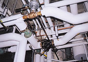
On another project at the UM Montana Tech campus in Butte, the building's hydronic heating system employed a packaged, skid-mounted, steam-hot water heat exchanger system. The assembly included the heat exchanger, hydronic circulation pumps, expansion tanks, steam control valve, relief valves, and other ancillary equipment mounted on a single, factory-design skid.Upon examination by the commissioning authority (CA), the expansion tank on the skid was much smaller than required by the original specifications. Although the design engineer and the package manufacturer had discussed the situation during the submittal stage, the tank that was supplied was too small. The undersized expansion tank caused pressures to rise excessively in the hydronic piping, causing the relief valve to open.
This protected the building and occupants, but also dumped a considerable amount of glycol-water solution down the drain by the time the problem was corrected. The relief valve trips were further aggravated by the placement of the relief valve on the outlet side of the main circulating pumps. The pressure rise at the pump outlet caused the valve to trip even more frequently. (The CA noted this problem and the valve was relocated to the inlet side of the pump.)
Finally, the pressure switch controlling the glycol-water makeup system had the wrong control range and could not accurately control the system makeup. The switch was causing the glycol makeup pump to increase the system pressure with more glycol, further worsening the relief valve tripping. (The glycol makeup tank is shown in Figure 1.)
It was only after all three of these discrepancies were identified and addressed that the system could be made to work reliably. All of these discrepancies were identified by the CA as part of the commissioning process.
Attic Piping: Protect It With the EMS
In the UM classroom building described above, there remains a persistent problem with freezing pipes in the attic space. These particular pipes are for fire protection sprinklers, but the same situation could occur with any hydronic piping that is not glycol-protected.The building was designed with the piping in the attic space, just above the ceiling of the floor below, and under a thick layer of insulation. The design team felt that the insulation layer and the proximity of the piping to the heated space below would prevent freezing.
However, in spite of all attempts to seal the attic space from drafts, the piping is still subject to freezing during cold, windy weather. Several pipe bursts have occurred, causing significant building damage and disruption. Investigation continues into the cause of the air leaks, but in the meantime the pipe breaks had to be stopped.
The campus staff was able to implement a fix in the form of an energy management system (ems) alarm point. A surface-mounted pipe temperature sensor was mounted on one of the pipe branches in an area of previous pipe break problems. This point was programmed to alarm when the pipe dropped to a temperature of 40°F. Although the attic sealing seems to have helped the situation, it was only the presence of this alarm that prevented another disastrous pipe break during a cold, windy night last winter. The alarm gave the campus staff time to return to the campus, drain the system, and set up a temporary fire watch until the severe weather passed.
In a building with an emcs, the owner can, and should, add points to protect equipment from freezing as experience dictates.
Vfd's: A Better Way to Control Pumps
Variable-frequency drives (vfd's) have been used for decades to control motors in applications requiring variable-speed operation. They provide a flexible, efficient means of controlling hydronic pumps in heating and cooling systems. Vfd's frequently are supplied with integrated motor-starter circuitry that offsets a portion of their increased cost when compared to the traditional magnetic motor-starter arrangement.For small pumping loads, vfd's may not be cost efficient. For motors of 5 hp or less, the application of a vfd may not have an acceptable payback in terms of energy cost savings. The necessity for accurate control may not be there either. However, for pump motors of 7.5 hp or higher, vfd's should be given strong consideration.
In the recent case of the new classroom building on the UM campus, a pump and vfd combination was value engineered out of the project in favor of two smaller hydronic pumps with magnetic motor starters. Some money was saved, but the resulting control problems were not anticipated. Staging the two pumps to operate in sequence according to system pressure looked good on paper, but turned out to be very difficult.
The cause of the difficulty was the use of three- and two-way control valves in the system and the large number of such valves. This created an unpredictable combination of system characteristics that made it virtually impossible to ensure the hoped-for staging when the pumps were controlled by the pressure in the system. The large change in system pressures that occurred with the activation of the second pump caused uncontrollable responses in the system. After much discussion and experimentation, controlling the pumps based on outside air temperature solved the problem. While this is not the most energy-efficient method, it is reliable and bypasses problems with the system's hydraulic characteristics.
Vfd Buyer Beware
When vfd's are used, the owner should confirm that the design engineer has considered at least the following.
- Is a high or low carrier frequency drive best for this application? In general, high-frequency drives are quieter but lower in efficiency. They are also potentially harder on motors.
- How long is the cable length between the drive and the motor? Short cable lengths are best, but may be difficult to achieve due to a machine room layout. If cable lengths are roughly 50 ft or longer, the owner should confirm that vfd and electric motor factory-authorized personnel have been consulted about the design.
- Are special motors required for the vfd application? Insulation breakdown and arcing are potential problems for motors used with vfd's, especially with high-frequency drives and long cable lengths. Vfd's generate harmonic voltages and currents that can result in overheated neutral conductors and equipment. These harmonics can also interfere with security and communications systems. Filters and specialized transformers can be installed to limit this effect. Have they been?
- Finally, are factory start-up, programming, and documentation included in the installation? This is an instance where new construction commissioning really pays off.
Dual Backflow Preventers?
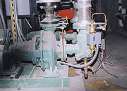
Sometimes, even a single pump system can be hard to control. At a new agricultural research building at MSU in Bozeman, biological containment required two separate domestic hot water supply loops. Each loop had to be protected from the other, and from the rest of the building, with backflow preventers (BPs).Also, each loop was equipped with its own circulating pump to ensure that each loop provided instant hot water at every point.
During the value engineering process, one of the two pumps was deleted in favor of using a single pump (Figure 2). The circulation requirement was small and so it appeared an easy task to substitute a single pump with sufficient capacity for the job. The BPs had been sized to cause minimal pressure drop.
Unfortunately, minimal pressure drop turned out to be the problem. Specifically, each BP required a certain back pressure to open, but once open, exhibited a reduced pressure drop. When the pump came on, one of the two BPs opened and flow was established in that loop. This reduced the pressure required for circulation; the pump responded by producing a higher flow with a smaller pressure differential. At this point the pressure was insufficient to open the other BP.
The result: One of the two loops was cold because it had no water circulation. The solution: Put the second pump back into the design. With both pumps operating, each BP opened in a positive and reliable manner.
Final Thoughts
Hydronic systems are firmly entrenched in modern institutional buildings, and their uses are expanding steadily. As buildings get more and more complex, the interaction between hydronic systems and other building systems also get more complex. This causes unforeseen problems in the field, but can also provide solutions.Here are some examples:
- Use glycol antifreeze to prevent freezing where possible. If that's not possible, include at least two other methods of preventing freezing. (After all, one of the two may fail.)
- Use the building emcs to cycle hydronic systems to prevent freezing based on input from the outside air temperature sensor, or use the emcs to issue an alarm if hydronic piping and equipment cool to a dangerous level and drain the systems before damage occurs.
- When using vfd's, check that the designer has consulted the factory with regard to carrier frequency, noise, cable length, and the potential for high-voltage motor damage.
- Also, check that neutral conductors have been sized large enough for increased currents due to vfd-induced harmonics.
- Use the value-engineering process in a thoughtful manner. It should not be a process of redesigning the hydronic system.
In spite of the examples cited above, the buildings included in this article are working fine. The problems were either solved during the construction process through the engineer's punchlist or commissioning, or the operating staff will solve them. But all parties agree that solving the problems during design is best. ES
