Let's continue our discussion on this topic, focusing on basic operating principles of alternating current (ac) variable-speed drives (vsd's) as applied to three-phase, ac induction motors.
Why Use VSD's?
A vsd, also referred to as a variable-frequency drive (vfd) or adjustable-speed drive (asd), is a power-conversion device that varies the speed of a three-phase induction motor. The basic principle used by the vsd is to vary the frequency of its output, which, in turn, varies the speed of the motor.Vsd's have become an important component in building power systems from the standpoint of energy savings. Centrifugal pumps, as well as centrifugal and vaneaxial fans, have variable torque loads. The torque required to drive the fan or pump is proportional to the square of the speed. Since torque and horsepower (hp) are related to each other as a function of speed, the hp requirement is proportional to the cube of the speed.
This relationship indicates that if the speed of the fan or pump can be modulated, the hp required to drive the fan or pump increases or decreases by the cube of the speed. Therefore, the use of a vsd enables us to deliver only as much power to the motor as is required to drive the load.
Consider a hypothetical ducted variable air volume (vav) system in which the calculated static pressure drop and airflow characteristics require a 50-hp supply fan motor for peak conditions. However, airflow requirements may often be less than the worst-case design condition.
When we remember that there are circumstances such as partial occupancy, we can take advantage of lower load requirements. Some vav boxes can be pinched down and fan speed can be reduced by a vsd. For our example, if the fan speed can be reduced to 80% of full speed, the corresponding system requirement is now a little over 25 hp, about half of the system's maximum capability.
This highlights the magnitude of opportunity for saving energy by applying vsd's. Not only are there operating cost savings from lower energy bills, many utility companies also have rebate incentives that may pay a portion of the capital costs associated with retrofits.

Concepts
Let's recap by remembering that the speed of an induction motor is proportional to the frequency of the ac voltage applied to it, as well as the number of poles in the motor stator. This is expressed by the equation:RPM = (f x 120) ? p
Where f is the frequency in Hz, and p is the number of poles in any multiple of 2.
Therefore, if the frequency applied to the motor is changed, the motor speed changes in direct proportion to the frequency change. The control of frequency applied to the motor is the job given to the vsd.
The vsd's basic principle of operation is to convert the building's electrical system frequency and voltage to the frequency and voltage required to drive a motor at a speed other than its rated speed. The two most basic functions of a vsd are to provide power conversion from one frequency to another, and to enable control of the output frequency.
VSD Power Conversion
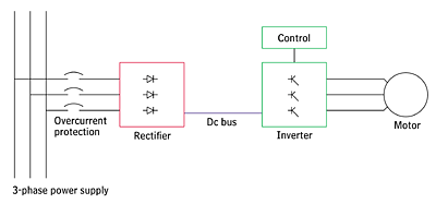
As illustrated by Figure 1, there are two basic components, a rectifier and an inverter, to accomplish power conversion.The rectifier receives the 60-Hz ac voltage and converts it to direct current (dc) voltage. A dc bus inside the vfd functions as a "parking lot" for the dc voltage. The dc bus energizes the inverter, which converts it back to ac voltage again. The inverter can be controlled to produce an output frequency of the proper value for the desired motor shaft speed.
There have been various types of inverters since the inception of the technology. Ideally, the inverter should produce a perfectly smooth sine wave, like the input. Practically speaking, this is difficult to achieve. The earliest inverters had limited control capabilities. They were able to provide ac output voltage in steps of constant voltage imprecisely following a sine wave, commonly referred to as the six-step waveform.
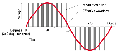
The most common type of inverter used today is the pulse-width-modulated (PWM) type. It simulates a sine wave by supplying the motor with various "widths" of voltage throughout the voltage cycle. When averaged together over the length of a cycle, the voltage "segments" look like a sine wave to the motor.
The voltage pulses are accomplished with the use of transistors, which act like on-off switches to provide varying pulse-widths of voltage to the motor. This is done in positive and negative pulse groups; each positive and negative group represents one cycle.
The illustration in Figure 2 represents a schematic of the transistor output of the inverter. The actual output of a vsd may be a little different depending on its output filtering.
One common complaint with early PWM drives was the objectionable noise created by the carrier frequency, or the transistors' speed of switching. Relatively low switching frequencies caused vibration in motor laminations to produce audible noise, which was transmitted through ducts and the building structure to occupied areas. This has been remedied by the use of isolated-gate bipolar transistors (IGBTs), which can be operated at higher frequencies, putting the associated noise above the audible range for the human ear.
Some of the advantages of the PWM inverter include constant power factor at all loads and speeds, efficiency as high as 98%, ride-through of power losses up to several seconds, a wide range of control capability, and the ability to withstand fairly wide line-voltage fluctuations.
There are two modes of operation with respect to base speed for a vsd, the constant-torque mode and the constant-horsepower mode. In the constant-horsepower mode, the vfd drives the motor above its rated frequency (hence, speed) and in order to do so, must sacrifice torque. Therefore, this mode of application is not typically used for fans and pumps, since their torque requirements increase with speed. These applications require that the vsd be applied in the constant-torque mode, which is applicable up to 60 Hz (for U.S. systems). In this speed range, the motor is enabled to deliver its rated torque.
In the constant-torque mode, the vsd maintains output voltage and frequency in proportion to each other. This is called the volts/hertz ratio, typically 7.6 V/Hz for a 460-V motor. If this ratio is exceeded, the motor core becomes "saturated" with magnetic flux. Figure 3 illustrates the volts/hertz ratio for 230- and 460-V motors.

Power Conversion Control
The first generation means for control of a vsd's power conversion is referred to asscalar control. Within the drive, it is an open-loop control system, which simply maintains output frequency scaled to output voltage.The scalar control method does not utilize a "proportional-integral-derivative" (PID) algorithm and does not utilize feedback internally. For this reason, its torque control capabilities are not sufficient for demanding applications which have been historically reserved for dc motors and drives.
A closed-loop scheme using PID control can be applied externally to refine the output of a drive with scalar control. The control algorithm had been external to the drive, but drives now generally include on-board PID control capability, requiring only a process sensor input to do on-board, closed-loop process control.
The second generation control method, called vector control, is becoming more prevalent in building system applications. This prevalence is due to the mainstreaming of technology into the marketplace rather than technical demands. Typical hvac applications do not require precise torque or speed control such as, for instance, an elevator does.
The intricacies of this method are beyond the scope of this article, but at a conceptual level it enables feedback to be utilized to maximize motor and drive performance. The feedback can be directly provided from a tachometer or encoder, or indirectly by storing known motor parameters in drive memory.
Some drives have the capability of "learning" the motor characteristics to which they are mated. The feedback is utilized in an on-board, closed loop control algorithm to provide precise speed, torque, and power control, with quick response to changes in load conditions.
Conclusion
Considering the prevalence of electric motors and associated drives in today's building systems, a basic understanding of these components is indispensable.The operational principles of this motor enable the use of frequency conversion by a vsd to modulate the speed of the motor, with the additional benefit of saving energy.
Final installment next month: Addressing the application of motors and drives, especially with regard to their use together. ES
