On large systems, the designer is often responsible for interfacing several controllers to create an overall system control. Although this can certainly provide a workable solution, it does increase both cost and complexity. When combining multiple controllers -especially if obtained from different manufacturers - the designer must be careful not to create inadvertent conflicts in operating logic.
Although there are situations where the "multiple box" approach is needed, there are others where control complexity can be reduced while still retaining desirable operating characteristics.
Keep It Simple AND Functional
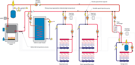
Recently, our firm was retained to design a hydronic heating system for a large custom home. The system was to provide radiant floor heating for the first and second floors of the house as well as for the entire basement. The owner also wanted to maintain the garage at a moderate temperature. In addition to space heating, the system would also need to supply domestic hot water for several bathrooms. The design space heating load of the home was about 200,000 Btuh.With the exception of the domestic water heating, all loads would use relatively low supply water temperature. If a conventional boiler was to be paired up with the low temperature/high thermal mass distribution system it would require protection against sustained flue gas condensation. There are several ways to do this using "intelligent" mixing devices such as motorized three-way and four-way valves as well as variable-speed injection pumps. The standard approach would be to use a separate mixing device for each space heating supply temperature required. An example of such an approach using multiple variable-speed injection pumps supplied from a common primary loop is shown in Figure 1.
This same approach could be used with the condensing boiler. However, forcing a condensing boiler to run at higher water temperatures, only to mix down before supplying the lower temperature load, essentially wastes the efficiency gains achievable through low temperature "condensing mode" operation. Since a condensing boiler was specifically requested by the owner, we wanted to maximize its efficiency while at the same time supplying all heating loads at the proper temperatures.
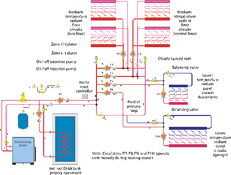
The system we designed was broken down into five zones. Two serve different areas of the basement. Another serves the first floor, and still another the second floor. The fifth zone serves the garage. The piping concept used is shown in Figure 2.
Water temperature in the primary loop is controlled by a simple boiler reset control. This is the only microprocessor-based control in the entire system. Upon a demand for heat, the reset control calculates the target temperature for the supply side of the primary loop based on outside temperature. It then fires the boiler as necessary to maintain the supply side of the primary loop close to this temperature.
Boiler water is delivered to the parallel primary loop through a pair of closely spaced tees. These tees uncouple the boiler shuttle circulator (P2) from the other circulators in the system. Flow through the boiler remains constant regardless of what distribution circulators are operating. This is an especially important detail, given the minimal water content and low thermal mass of modern condensing boilers.
The parallel primary loop has five crossover bridges, each equipped with its own small circulator. Each circulator comes on when its respective zone calls for heat, and it is equipped with an internal check valve to prevent reverse flow when off. When operating, circulators (P3) and (P4) send streams of water through closely spaced tees in their respective crossover bridges. These tees serve as the pick up and return points for the circuits supplying the first and second floor manifolds. The closely spaced tees also provide a U-turn for constant circulation in each zone, which was also a design objective. These tees also prevent flow interference between circulators regardless of what zones are operating.
Circulators (P5) and (P6) serve as on/off injection pumps. They provide the heated water input to the mixing process that lowers the temperature supplied to the basement and garage floor circuits. This will be discussed in more detail shortly.
Zone valves, along with a single circulator, were also considered in lieu of individual crossover circulators. However, flow rate variations in the primary loop, depending on which zone valves were open, were a concern. This situation could have been partially corrected by installing a differential pressure bypass valve, but that adds cost. We also found that small zone circulators with integral flow checks were less expensive than zone valves. The 2-in. parallel primary loop creates very little flow resistance between the return and supply side of the crossovers. This minimizes flow rate variations within the crossovers as various circulators turn on and off.

Keep the DHW Coming
Large homes often have several full bathrooms with high demand luxury fixtures. This house was no exception, and therefore domestic water heating was treated as a priority load. When the tank thermostat calls for heat, the boiler is allowed to climb to 180°F. This high temperature provides good heat transfer through the internal heat exchanger in the domestic hot water (DHW) tank (albeit at the loss of condensing mode operation). During the domestic water heating mode, circulator (P1) is turned on and boiler shuttle circulator (P2) is turned off, as are the zone circulators. The distribution circulators are also turned off for the relatively brief periods of DHW heating.
Ideally, the distribution circulators would provide constant circulation through the floor slabs during the DHW cycle, but this required another relay and more wiring. In keeping with the simplicity theme we felt the compromise was minimal. When the DHW load is satisfied the zone circulators and distribution circulators restart as necessary. The small volume of hot water in the boiler blends with cooler water from the return side of the primary loop before heading out to the floor circuits.
Temperature Transformers
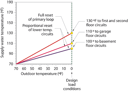
Under design load conditions, the gypsum thin-slab floor heating zones require water at 130°. Under the same conditions the basement floor circuits require water at 100°, and the garage floor requires fluid at 110°. To provide these lower temperatures to the basement and garage circuit we used the concepts of submixing and proportional reset control.Submixing uses one "intelligent" mixing device to supply the highest of the necessary mixed supply temperatures, while other "dumb" mixing devices reduce that temperature in other parts of the system. When the intelligent mixing device regulates the higher mixed water temperature using outdoor reset, the lower mixed temperatures also track along a reset line. This effect is called proportional reset and is illustrated in Figure 3.
In our system, pumps (P5) and (P6) inject water from the primary loop (130° at design conditions) into the distribution loops serving the basement and garage circuits. The rate of injection is calculated based on water temperatures at design load condition, and then set using the balancing valve. Whenever heat is needed by either the basement or garage circuits, the respective injection pump is on at full speed.
Because the temperature of the water in the primary loop is itself reset by the boiler controller, the outlet temperature from the injection tee in the basement and garage distribution systems is also fully reset. Hence, this approach provides three different and simultaneous water temperatures, all fully reset, without using a single modulating mixing control.
Although submixing worked well in this application, it does have limitations that designers should be aware of. First, since a nonmodulating mixing device (such as an on/off injection pump) can only provide fixed flow proportions of the incoming water streams, any variation in the temperature or flow rate of either stream causes a change in the mixed water temperature. Unlike a modulating mixing device, a fixed mixing device cannot compensate for such changing inlet conditions.
One example of where this could be a problem is a system that uses zone valves or circuit valve actuators downstream of the mixing point. As the zone valves open and close, there would be corresponding changes in the flow rate and temperature entering the mixing tee. This in turn would cause changes in the supply temperature to the distribution system.
Another situation would be a system in which zones undergo frequent and deep temperature setback and recovery. Again, a nonmodulating mixing device cannot compensate for the cooler return water coming into the mixing point during recovery periods. Although the system would eventually reestablish normal operating conditions, recovery periods would be substantially lengthened, especially for high mass distribution systems such as slab-type floor heating.
Finally, a nonmodulating mixing device cannot protect a conventional boiler from low temperature operation. Since there is nothing to modulate, the mixing device cannot serve as a "thermal clutch" between the conventional boiler and high mass/low temperature load. This could lead to sustained flue gas condensation during startup or recovery from setbacks. Rapid scale formation and fireside corrosion of the boiler heat exchanger and vent piping is the likely result of such operation.
In general, submixing is best suited to systems that require relatively steady indoor temperatures.

The Ice Storm Cometh
In cold winter climates, it is highly advisable to protect garage floor heating circuits from freezing. Although constant water circulation through the floor circuits would delay freezing, a prolonged power outage renders this a moot point. Like it or not, in the absence of heat and electricity, the only sure way to prevent freeze up is to install antifreeze.In other systems, we've often specified brazed-plate heat exchangers between the glycol-filled garage floor circuits and the balance of the system that operates with water. The heat exchanger, along with the associated glycol-side trim (expansion tank, air separator, pressure relief valve, fill/purge valves, and circulator), obviously add cost and further complexity to the system. Given the low operating temperatures of this system, such a heat exchanger would have a low approach temperature and thus would have to be rather large. Keeping with our goal of simplicity, we elected to fill the entire system with an inhibited propylene glycol solution and eliminate the heat exchanger. The fringe benefit is that the entire system is now protected against freeze up during a prolonged power outage.
In summary, here's what the system delivers:
- High operating efficiency for the condensing boiler by matching it with low temperature radiant floor panels.
- Full outdoor reset control of the supply temperature to the radiant panels to minimize variations in comfort.
- Constant circulation in all distribution circuits, allowing heat stored in thermal mass, as well as internal heat gains, to be redistributed within the zones when necessary.
- Priority domestic water heating allows the full 200,000 Btuh boiler output to be delivered to the DHW tank whenever it calls for heat.
- Simplicity of control: A simple boiler reset control and a multizone relay center provide all necessary operating logic.
Although these characteristic could have been provided through other hardware selections and operating logic, this approach provides good value engineering and simple, reliable operation. ES

