
Common Problems and Solutions
For many years, ammonia refrigeration system operators have been taught to operate their systems at the lowest possible condensing pressure (temperature). Most recommendations are to keep the condensing pressure at 100 psig, or even 90 psig, provided the entire system will operate properly. Most times the operators have multiple reasons for keeping the condensing pressure at 175 psig. The reasons given generally fall into the following categories:1. My defrost system won’t work unless I keep my condensing pressure 175 psig.
2. I can’t harvest my ice makers rapidly enough unless I keep my condensing pressure at 175 psig.
3. My plant engineer said that I can’t operate below 150 psig or 175 psig.
4. I have a flash gas pumper system that won’t work below 160 psig.
5. My ice cream freezer (Votator) must have 150-psig liquid ammonia so I keep my condensing pressure at 175 psig.
6. I have liquid-injection cooled screw compressors, and I can’t operate below 150 psig.
7. I try to control my condensing pressure at 100 psig, however I notice that quite often only one small compressor is operating and all of the evaporative condenser fans and pumps are operating.
There are ways to overcome each of these situations, and in turn, operate at pressure down to 100 psig (64˚F saturated). The savings in reduced compressor bhp and reduced evaporative condenser fan bhp and water pump hp can be estimated employing weather recorded data. Obviously those plants that operate in areas that have predominantly low wetbulb temperatures will save more energy than high wetbulb areas, however this is not always the case. Both areas can justify adding the programmable controllers and the system additions to optimize the evaporative condenser performance and save energy. In many cases, the cost to add these controls can be accrued from energy savings within six months to two years.
Let’s solve each of the seven excuses, one by one.
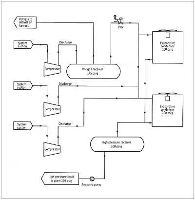
1, 2 & 3. These three are easy. Add a hot gas defrost receiver (HGDR) designed to hold enough hot gas for defrost and install an outlet pressure regulator set at 175 psig or the minimum pressure at which the defrost or harvest system will work. Direct the discharge of the smallest compressor that will supply the required hot gas to the HGDR. Then the condensing system can operate at 100 psig or lower.
4. See solution to #1, #2, and #3 above. However, the best solution is to convert to a mechanical pumping system and save 4% to 15% of the energy required, depending on the specific application and its operating temperature.
5. Another problem easily solved. Add dual liquid pumps (one spare) to the high-pressure receiver or provide a small liquid receiver in the condenser drain line to supply the ammonia to the pumps. Select them for 60 psig differential and the condensers can be operated at 1,000 psig. The pump hp will be minimal.
6. See solution to #5 above. However, the best approach is to convert to the thermosyphon cooling and save 4% to 10% of the energy required by injection-cooled compressors. Two stage system conversions may save more.
7. The solution for this also applies to solutions in items #1 and #6 above, and all multiple-evaporative condensers. An evaporative condenser microprocessor controller properly applied and programmed will provide continuous control of the condenser system, a control that will set the condensing pressure at its most efficient point at all times, by measuring the wetbulb temperatures.
In order to explain this problem, let’s envision an equipment room with several large screw compressors that operate during the production cycle and a small compressor (75 hp) that is a night, weekend, or off-production unit to supply refrigeration to the holding freezers or coolers. The evaporative condensers on the roof have a total of 125 hp in fan hp and pump hp. The condensing pressure controller is set at 100 psig (63˚F), and its 80˚F wetbulb (wb) outside. We have 125 hp of condensers operating and only 75 hp of compressor because we cannot attain 100 psig condensing at 80˚F wb.
Now comes our microprocessor controller. It recognizes that the condensing pressure cannot reach the 100-psig condition as it is set to maintain a condensing pressure that is some higher than the wetbulb ˚F. Thus, it would cycle the evaporative condenser fans and pumps to arrive at the most efficient condensing pressure. See Figure 1 for an energy efficient system flow diagram.
Microprocessor Control
A typical microprocessor-based evaporative condenser control system is a system that measures the temperatures and pressures of the system by the use of highly accurate analog temperature and pressure sensors. The use of programmable or microprocessor control allows the owner to realize condenser operation benefits that are not available with relay logic controls.The measurements made by the unit are air temperature (drybulb temperature), wetbulb temperatures (which is related to relative humidity), condensing temperature, and condensing pressure. The output of the condenser control operates the water pumps and fans to achieve maximum efficiency. The temperatures and pressures are normally displayed on the Touch Screen Operator Interface on the panel. This unit allows the operator to monitor the system operation, and to change operating parameters.
The controller will turn on condenser water pumps and fans until the design range between the wetbulb temperature and condensing temperature is reached. Thereafter, if the temperature differential goes up, the condenser capacity will be increased. Likewise, if the temperature differential goes down, the computer will turn off fans and water pumps to maintain proper efficiency. There is an adjustable delay between changes in capacity.
As the wetbulb temperature changes, the microprocessor constantly adjusts the condenser capacity to maintain the set differential adjustment above wetbulb. This would be the equivalent to the operator standing at the condenser making new adjustments every five minutes all year long!
There is an additional factor in condensing efficiency. If air and other non-condensibles are introduced into the refrigeration system, the condensing pressure increases. A pressure-temperature chart for ammonia provides the correct pressure for any given temperature. If there is a non-condensible in the system, the pressure will be too high. As the condensing temperature is measured, the controller calculates the associated ammonia pressure. If the measured pressure is 3 psi to 5 psi above the calculated pressure, the system has non-condensibles in it. The controller automatically turns on the purger. If the purger has run for a reasonable time and the pressure has not corrected back to approximately the correct pressure, an alarm is sounded. If there is no purger, an alarm is sounded. The operator can then manually purge the system at an opportune time.
The condenser control also measures outdoor temperature. The Touch Screen Interface displays the temperature. It also offers the operator a choice of turning off condenser water pumps when the temperature is below freezing, or automatically turning on a condenser pan heater, and/or turning off the water pump.
Four Cities: A System Analysis
Our example system (Table 1) has three 300-hp compressors, 60 hp of condenser fans, and 15 hp of condenser water pumps. It also has a 75-hp compressor for duty when the production process is off. The ammonia condensers were designed for 95˚F saturated condensing temperature (SCT). The total compressor duty at saturated suction is 10˚F. At 181.1 psig (95 SCT), each compressor bhp is 302. At 126 psig, it is 229. At 103 psig, it is 200. The design wetbulb is recorded in Table 1. By employing the microprocessor condenser controller, analyze a full year (8,700 hrs). Compare this to operating the system 8,700 hrs at a fixed condenser pressure of 175 psig. Assuming the full compressor load and a design approach between the wetbulb and condensing temperature for all wetbulb temperatures, as shown in Table 1, the differential or approach between condensing temperature and the wetbulb temperature is 15˚F. For El Paso, it is 25˚F.Few, if any, plants will operate 8,700 hrs/yr at full load. However, this comparison is made strictly as an example. The calculations can be modified to fit any combination of hours and operating conditions on an hourly basis. It is obvious that there is a major energy savings by employing the wetbulb controller.
Table 1 is the compilation of data for four cities that have highly varying wetbulb ˚F conditions. This analysis includes the three 300-hp screw compressors only.
Even if the plant operates only at full load, 2,000 hrs in lieu of 8,700 hrs, there is a savings of around $24,000 in the Little Rock, AR example, and Little Rock is a high wetbulb area. The wetbulb condenser controller and hot gas accumulator can normally be installed for less. There are other savings that are not included in Table 1 that can be attributed to the wetbulb controller, such as cycling condenser fans and pumps. Some evaporative condenser control systems employ a thermostat in an evaporative condenser water pan. Where multiple evaporative condensers are employed, picking the proper condenser pan for measurement may be a problem unless the system has an indoor water sump. The wetbulb sensor is a much more accurate control. Wetbulb evaporative condenser controls are a major step in reducing energy consumption in industrial refrigeration systems. ES
