Principle of Operation
Magnetic flowmeters use Faraday's Law of Electromagnetic Induction to determine the velocity of a liquid flowing in a pipe. Faraday's Law forms the basis for electrical generation systems where wires travel through a magnetic field and produce a voltage.In a typical physics class experiment to illustrate the phenomenon, a wire (conductor) connected across a galvanometer can be moved through the magnetic field of a horseshoe magnet and cause the galvanometer pointer to move. Moving the wire in the opposite direction will cause the pointer to move in the opposite direction due to the changing voltage polarity. Moving the wire faster will cause more voltage to be generated and the meter movement to move higher.
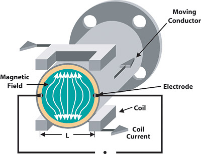
In magnetic flowmeters, a magnetic field is generated and channeled into the liquid flowing through the pipe. To accomplish this, the electromagnetic coils can be located outside of the pipe (flow tube), however the flow tube must be nonmagnetic to allow penetration of the magnetic field into the liquid. Locating the coils internally to the flowmeter (closer to the liquid) can reduce the electrical power necessary to deliver the magnetic field, as well as reduce the size of the flowmeter and fabrication costs.
Following Faraday's Law, flow of a conductive liquid through the magnetic field will cause a voltage signal to be generated. This signal is sensed with electrodes located on the flow tube walls. When the coils are located externally, a nonconductive liner is installed inside the flow tube to electrically isolate the electrodes and prevent the signal from being shorted. For similar reasons, nonconductive materials are used to isolate the electrodes for internal coil designs.
The fluid itself is the conductor that will move (flow) through the magnetic field and generate a voltage signal at the electrodes. When the fluid moves faster, more voltage is generated. Faraday's Law states that the voltage generated is proportional to the movement of the flowing liquid. The transmitter processes the voltage signal to determine liquid flow.
Electromagnetic Excitation
The voltage signal will take the same general form as its electromagnetic excitation. When a magnetic flowmeter is excited by a sinusoidal magnetic field (AC waveform), the signal generated at the electrodes is also sinusoidal.In earlier designs, these signals were subject to a number of influences that affected measurement quality, including stray voltages in the process liquid, capacitive coupling between the signal and power circuits, capacitive coupling between interconnecting wiring, electrochemical voltage potential between the electrode and the process fluid, and inductive coupling of the magnets within the flowmeter. These flowmeters required a zero adjustment to compensate for these influences and the effect of electrode coating.
Turning the electromagnetic field on and off (DC waveform) causes the signal to resemble a square wave. When the electromagnetic field is on, the signal due to flow plus noise is measured. When the electromagnetic field is off, the signal due to only noise is measured. Subtracting these measurements cancels the effects of noise and eliminates the zero adjustment, reducing the abovementioned drift problems, and improving performance.
Waveforms other than those described above are also in use.
Measured Quantity
Measuring flow entails the measurement of the quantity of fluid passing a given point in a conduit. However, this does not clearly define the measurement requirement, due to the various types of flow and the different measurement principles used to measure flow. The following equations express the relationships between the types of flow.Q = A
W = r
Where:
Q = volumetric flow rate;
A = cross-sectional area of the conduit;
v = average fluid velocity;
W = mass flow rate; and
r = fluid density.
Referring to the above equations, the volumetric flow rate is the volume of fluid that passes through the flowmeter per unit time. Flowmeters that measure fluid volume directly should be considered volumetric flowmeters.
Some flowmeters measure the average fluid velocity. The volumetric flow rate can then be inferred from the average fluid velocity when the cross-sectional area is known. Uncertainty associated with the cross-sectional area can degrade the inferred volumetric flow measurement. Flowmeters that measure velocity should be considered velocity flowmeters.
The mass flow rate is the mass of fluid that passes through the flowmeter per unit time. Flowmeters that use the properties of mass to measure the fluid mass should be considered mass flowmeters. Some flowmeters (sometimes also called mass flowmeters) infer a mass flow rate from measurements using fluid properties that are assumed to be constant, or from multiple measurements that are used to compensate for changing fluid properties. Uncertainty associated with fluid properties can degrade the inferred mass flow measurement.
Inferential flowmeters measure a quantity related to the velocity head (1⁄2 p v2). The volumetric flow rate can then be inferred when the density is known. Uncertainty associated with the fluid density can degrade the inferred volumetric flow measurement. Inferential flowmeters do not measure volume, velocity, or mass, but rather a quantity related to velocity head, from which a volumetric flow rate can be inferred.
The above equations describe the mathematical relationship between the volumetric flow, fluid velocity, and mass flow rate. Given a volumetric flow rate, fluid velocity, or mass flow rate measurement, the other two types of measurement can be calculated when the fluid density and/or cross-sectional pipe area are known. Uncertainty associated with the fluid density and/or cross-sectional pipe area can degrade the calculation. Flowmeters are sometimes calibrated in units of a type of flow that is different from the type that is measured by the flowmeter. This may mislead an observer as to which type of flow is truly being measured by the flowmeter.
The magnetic flowmeter signal is proportional to the fluid velocity. Therefore, these flowmeters measure velocity, from which the volumetric flow rate is inferred utilizing the first equation, assuming that the cross-sectional area of the conduit is known. Magnetic flowmeter performance is therefore predicated on how well the average fluid velocity is measured and how well the cross-sectional area is known. Uncertainty in the cross-sectional area can degrade the inferred volumetric flow rate measurement.
Magnetic flowmeters are among the most applicable of the velocity meters. The major criteria for success in a magnetic flowmeter application are a conductive fluid and a full pipe with minimal air entrainment. But those are not the only considerations.
Piping and Hydraulic Installation Considerations
In general, the flowmeter primary should be located in the piping such that it can function hydraulically. Here are some pointers:
- Locate the control valve downstream of the flowmeter.
- Keep the flowmeter full of liquid using appropriate hydraulic design. Locating the flowmeter in a vertical riser is preferred. In horizontal pipes, the downstream piping should rise above the flowmeter elevation. Do not locate the flowmeter where noncondensable gases can collect, such as in an inverted U-tube arrangement.
- Be especially careful with the piping design in services where the liquid is flowing using gravity.
- Calculate performance at anticipated flow rates. A smaller flowmeter may provide better accuracy, but pressure drop and abrasion considerations may indicate the appropriateness of the larger flowmeter.
- Define straight run requirements. The straight run piping should contain no fittings, such as elbows, tees, or reducers. When additional straight run is available, locate most of the additional straight run upstream.
- Use the proper mating flange. In particular, do not install 0.5-in. wafer flowmeters between 1-in. flanges. While performance can be degraded by this installation, the larger concern is leakage due to the smaller sealing surface that this combination provides.
Flowmeter Performance
One of the most important differentiators between models of magnetic flowmeter, besides physical features, is performance. It has been largely impossible for an enduser to determine the relative performance of all of the magnetic flowmeter models from which they may choose. Recently, such an agreement has been produced.In that comparison2, tabulated and graphical performance data revealed significant differences between models and manufacturers of magnetic flowmeters. To help select the best equipment for an application, users would also like to know which models perform better within a given category of magnetic flowmeters. To this end, within each category, each model was ranked in order of its calculated performance. Some magnetic flowmeter performance was as much as two to three times poorer than that of other flowmeters in the same category.
The calculations necessary to produce the magnetic flowmeter concordance illustrate much of the reason why magnetic flowmeters might be perceived as a commodity product. Magnetic flowmeter performance specifications are often intricate, yet suppliers often simplify them to reflect performance only under the best operating conditions. So incredibly "simple" have things become that some suppliers cannot quantify the accuracy of the analog output signal. Yet this is important, since the analog output is the signal most commonly used to control the process.
The Consumer Guide to Magnetic Flowmeters concludes "... while there are differences in the electronic features associated with different transmitters, flowmeter performance at reference conditions was found to vary widely. Differences were especially significant at low flow conditions that are commonly encountered in actual flowmeter operation."
This book, and the series of which it is a part, are unique in providing this comparison data. The results are significant and are expected to alter buying patterns and marketing strategies. Because of the dynamic changes in the flowmeter marketplace due to acquisitions, and product additions/deletions, these The Consumer Guide to ... books are updated as events warrant, making them available as useful sources of timely information on a continuing basis. ES
Other books in the Consumer Guide to ... series include:
- The Consumer Guide to Coriolis Mass Flowmeters;
- The Consumer Guide to Differential Pressure Flow Transmitters;
- The Consumer Guide to Magnetic Flowmeters;
- The Consumer Guide to Ultrasonic Flowmeters (available in early 2004); and
- The Consumer Guide to Vortex Shedding and Fluidic Flowmeters.
All of these books are available at the ISA Bookstore (www.isa.org).

