
Temperature sensors are used as part of the control package to alarm or shut down the AHU in order to prevent coil damage. Sensors are also used to prevent air below a low temperature limit setpoint from being discharged into the occupied spaces. The choice to only alarm or to shut the unit down is relative to the type of space the unit serves. Hence, shutting the unit down may be a major problem in facilities such as hospitals, laboratories, or process environments.
The typical air handler has these basic components: outdoor air intake, return air connection, control dampers, mixing area, filter bank, heating coil (pre heat or basic heat), cooling coil, reheat coil, fan, and the appropriate control sensors. Low-temperature conditions must be considered for each of these components in order to prevent operational problems that would affect the occupied space conditions.
Outdoor Air Intake
The air may be introduced through a wall louver or a roof hood. There are many types of louvers and hood inlets available. The recommended inlet velocity for the type of intake selected will minimize the snow and rain carryover into the AHU. However, even with this design consideration there will be certain conditions in which snow and/or rain will enter the unit. A plenum, drain pan, or ductwork attached to the inlet should be watertight and have a pitch path to the drain location. Snow will also be deposited in the plenum area or in low areas of the outdoor air duct. The ultimate solution for snow removal in these zones is to either shovel it out or melt it.
The snow can be melted at the preheat coil face if the prefilter is removed in the winter. However, if the choice is to protect the preheat coil from airborne contaminates with the prefilter, then consideration must be given for snow buildup on this filter. Accumulation of snow on the prefilter bank may cause the bank to collapse. Collapse can be prevented by providing a spring-loaded hinged section to one or more of the filter racks, which will open to bypass the filter if the pressure differential across the filter bank becomes too great. Providing a heat-ing source at the prefilter is also an option. A unit heater blowing onto the filter bank or a radiant heater aimed at the prefilter will melt the snow and prevent filter bank collapse. The snow melting system can be turned on/off by a moisture detector on the filter face.
Control Dampers
One type of an outdoor air supply unit is the gas-fired makeup unit, which may be mounted on the roof or indoors. These units also come in direct-fired or indirect-fired configurations. The open/closed flow damper location is critical, because if the damper is in the wrong location, it will freeze closed. The proper damper location for a rooftop unit is at the fan's discharge in the warm space. If the unit is mounted indoors, the damper can be mounted at any location in the intake air path.The type of control dampers for the outdoor air and the return air are also a design consideration. If the control dampers are close to the unit and configured to aid in air mixing, the proper choice is either parallel or opposed blade dampers. Outdoor air dampers with a weather louver/birdscreen nearby should be the opposed blade type. If the outdoor air is away from the intake, a parallel blade damper should be used. If both the outdoor air and the return air dampers are parallel blades, they should be directed at each other to facilitate the air mixing.
Other damper arrangements include a dedicated minimum outdoor air damper with a modulating economizer damper, a return damper with a larger pressure drop (for control purposes) than the outdoor air damper in an exhaust air/relief air arrangement, and the use of a face and bypass damper set at the heating coil. The heating coil in a face and bypass arrangement should be on the lower portion of the unit to heat the cold air that falls to the bottom of the unit casing. The face velocity across the bypass damper should not exceed 2,500 fpm.
Mixing Area
The zone of the AHU where the outdoor air and the return air join is often called the "mixing box." The purpose of this area is to blend the cold air with the warmer air before it passes to the preheat or heating coil. There are many options available that provide mixing of airstreams and subsequently prevent stratification of the cold air as it passes through the coil assembly. The simplest concept is to place the outdoor and the return air dampers close together and direct the warmer return air at the cold outdoor air entering through the damper blades. Figure 1 shows a baffle under the return air damper that is sometimes used to direct the return air to the outdoor air damper.
A blender section may also be used to further mix the warm and cold air streams. The traditional design velocity through the blender section is 1,500 fpm. However, if the system is a variable volume system, the 1,500 fpm should be the winter cfm, which is usually a reduced cfm from the design cooling cfm. This variable cfm capacity with its variable velocity through the blender unit must be a design consideration or the blender section will not effectively mix the two airstreams.
Coil Protection
Unit coils using steam, hot water, and chilled water to provide the required discharge air conditions all contain a liquid that freezes when the outdoor air percentage and the outdoor air temperature result in subfreezing conditions at the coil surface.Steam coils are often used in a preheat configuration and are the first coil to see the subfreezing air. The freezing liquid in a steam coil is the condensate. Steam coils must be pitched toward the steam trap location. In factory-built units, the coils are often installed level and do not drain well. Also, in coil banks over 8-ft long, the coils tend to have a low spot in the center due to coil tube sag.
The condensate tends to freeze in operation slightly below the freezing point due to the modulation of the control valve. Two sets of control valves can be used: a small open/closed valve for operation near the freezing point with a larger valve to modulate as required to control the temperature setpoint. However, the open/closed valve should be sized to not allow the cabinet temperature to exceed 150°F during a unit shutdown. The condensate piping before the steam trap must have a cooling leg long enough to ensure that condensate is collected before the steam trap. A vacuum breaker/air vent should also be used on the coil piping whenever a modulating steam control valve is used, to allow the condensate to drain to the steam trap.
A heat transfer fluid solution (glycol) should be used in hot water and chilled water coils for low temperature operation. The percentage of the heat transfer fluid solution varies with the low temperature protection required. However, the old rule of a 50% solution is not practical or required for protection. The greater the percentage of the heat transfer fluid, the greater the heat transfer reduction capacity of the coils. This factor must be considered in the design. A greater flow rate is required to compensate for the capacity reduction. Additional pumping hp is required due to the higher viscosity of the fluid and the greater flow required. Always specify an inhibited glycol heat transfer fluid, rather than just calling for ethylene glycol. A specification based on ethylene glycol will often result in industrial strength type fluid being installed without the proper corrosion protection.
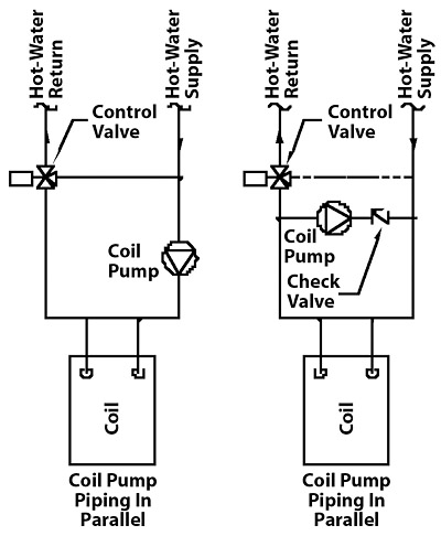
A coil pump may be used to protect the coil from freezing. These pumps are small fractional hp inline units that operate when the mixed air conditions approach freezing conditions. Figure 2 shows how the pumps may be piped in a series or in a parallel configuration. The series configuration depends on the primary pump operating, and the parallel configuration will offer protection if the primary pump is "off."
Sensors
Low-temperature capillary tube-type sensors are traditionally used on the discharge face of the heating and cooling coils. If the air temperature falls below the low temperature setpoint, then the control signal will shut down the unit. This process then will require a manual reset to restart the unit. This may be acceptable for an office-type air system but is not appropriate for hospital, laboratory, and process type units. An alarm notice is the appropriate signal for a critical 24/7 type of operation. The operating personnel then can decide what steps to take to handle the low-temperature coil conditions.Other Conditions
Building stack effect can cause cold air to enter through closed outdoor air dampers when the unit is in the off condition. This can also freeze liquid in the coils that are in a non-flow status. Technology has now provided an option of low-leakage dampers, which should be used on all the outdoor air dampers on an air-handling system subject to stack effect.
Cooling coils can be drained for operation in winter weather. After draining, the coils should also be flushed with a heat transfer/water mixture and then drained again to ensure that any remaining liquid in the coil is protected from freezing. The freeze sensor on the cooling coil can be switched off after the coil has been drained to prevent nuisance alarms.
Reality
The operations staff will often disconnect the low temperature sensors if the alarm process calls for a unit shutdown. Shutdowns mostly happen during unoccupied periods, and the operations staff does not like to respond to these alarms in the middle of the night. Rather than disconnecting the sensors, the signal should be an alarm to be dealt with when the operations staff feels it is appropriate. Another option is to move the low temperature sensor to a discharge duct location, which will signal a major problem rather than a minor air stratification problem at the coil.
A chilled water coil with a circulation pump creates a piping insulation problem. Because this circulation arrangement contains a large number of fittings near the coil, it is difficult to maintain a continuous vapor barrier on the chilled water piping, valves, and fitting. The result is mold in the insulation. A solution is to leave the pump uninsulated and put a drain pan under it.

