
Grace Church is a 339,000-sq-ft facility (Phase 1 construction) located in Eden Prairie, MN that includes a 4,500-seat auditorium known as the Worship Center, meeting rooms, child and adult education centers, a gymnasium, a bookstore, a full commercial kitchen, staff offices for 100 people, and two reception halls. The project budget for the first phase of the project was $38 million. Future expansion plans for the facility are in progress, and will include a chapel, a fellowship hall, and larger adult education facilities.
Mechanical Design for Acoustic Excellence
Before discussing the project, a brief description of some of the fundamental properties of architectural acoustics is warranted.Sound pressure vs. sound power. One of the most common pieces of data HVAC engineers deal with while designing systems is the sound data of the equipment being used for a given application.
What many fail to realize, however, is that sound power (a description of the amount of acoustic energy given off by a piece of equipment) and sound pressure (a measurement of the acoustic energy intensity in a given space) are not synonymous. HVAC equipment is rated in terms of sound power because sound power levels are independent of the room in which the levels are calculated.
On the other hand, sound pressure levels, to which the human ear is sensitive, are highly dependent on the acoustic properties of a given space. Obviously, since manufacturer data is reported in one system, and the levels of import are needed to be in another, a conversion must be calculated that takes into account the acoustic properties of the receiver space along with provisions for signal losses through the duct distribution network, if applicable.
Room criteria curves. Most HVAC designers are familiar with the “NC” rating of a room. In recent years, a more descriptive expression of the acoustic properties of a room has been developed. This is the room criteria, or RC rating.
To determine the RC rating of a given room, sound pressure level data is gathered for the 16, 31.5, 63, 125, 250, 500, 1,000, 2,000, 4,000, and 8,000 Hz octave bands.
RC ratings have two components. The first, a numerical component, expresses the approximate sound pressure level of the noise floor for the room. This number is an average of the sound pressure levels in the 500, 1000, and 2000 Hz octave bands.
The second portion of the RC rating is called a sound quality modifier. There are four primary sound quality modifiers used in RC ratings. These are: N for neutral, R for perceptible rumble, H for perceptible hiss, and PV for perceptible vibration.
Neutral rooms have sound pressure levels that are not greater than a given RC curve by more than 5 dB for any octave band from 31.5 to 250 Hz or 3 dB from 1 to 4kHz. Rooms that receive an “R” rating have sound levels that exceed their RC curve by more than 5 dB within the 31.5 to 250 Hz range. Similarly, “H” classified rooms exhibit background noise levels that exceed their target RC curve by 3 dB from 1 to 4 kHz.
Typically, the PV modifier is used in addition to the R modifier whenever plotted sound pressure level data lies within either of the boxed regions labeled A or B in the upper left of the chart. Figure 1 presents the base RC curves and sample cases for several room types.
In this example, the classroom is rated as an RC 34-N. The office is a good indicator of the value of using RC curves instead of NC. The base rating for the office is RC-39, which is typical for an open plan office. The modifiers, however, indicate a potential low frequency noise problem in the room. The sound pressure in the 125 Hz octave band exceeds the RC 39 curve by more than 5 dB, earning the room a classification of RC 39-R.
In addition, the sound pressure levels in the 16 Hz band fall within the vibration warning area B. Therefore, the complete description of this room is RC 39-R (PV-B). Occupants will likely report annoyance with the low frequency noise in the space, and sensitive individuals may experience uneasiness due to the low level vibrations in the room. Were the room to have been classified using older systems, none of this additional information would be known.
Duct velocity guidelines for acoustically sensitive applications. One of the most critical elements of a well-designed HVAC system for an acoustically sensitive room or building is the design duct velocity. While more efficient fan systems and better construction methods, resulting in lower duct leakage (and therefore higher static pressure delivery systems), have allowed design velocities for commercial buildings to rise in recent years, it is essential that duct velocities for performance spaces be limited to control generated noise levels. Table 1 presents recommended duct velocities for spaces with an array of RC ratings. These velocities have been arrived at through numerous projects and with the input from several acousticians, including the acoustician for the Grace Church project.
These values (especially those for the supply mains outside of the space) should be considered maximum design velocities. Proximity to the listener position has a strong effect on the perception of mechanical system noise as well. If supply and/or return mains are located at a sufficient distance from the audience, the velocities within the supply mains may be increased slightly. Still, the velocities at branches and terminals should be carefully selected to ensure that noise induced by turbulence is minimized.
Additionally, diffuser selection in performance hall applications is critical. In general, for rooms with an RC rating below RC 20, if a diffuser is used, a commercially available plaque-type diffuser should be considered with care taken to prevent dumping of cold air on space occupants. For large performance halls with very low RC rating targets, custom-designed diffuser plates or open ended supply terminals are recommended.
Grace Church: A Case Study
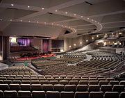
The size of the worship space in Grace Church elevates the client expectations for the hall above that which one might normally associate with a church. Upon its completion, the Worship Center at Grace Church is the second-largest enclosed auditorium in the state of Minnesota not built to share use with sporting events. It is the Church’s intent that the main auditorium will be used not only for holding religious services, but also for theatrical productions. Due to this distinction, there were significant client expectations not only for the aesthetics of the hall, but also for the acoustic performance within the space.Project Objectives
At the heart of the building system’s design were three primary goals. First, the mechanical and electrical systems had to meet strict acoustic performance criteria. Second, all systems in the building needed to operate with excellent energy efficiency characteristics without being difficult to maintain or operate without the presence of an on-site facilities engineer. Finally, the systems had to integrate with the building architecture to exceed the client’s performance expectations, both now and after future expansions.One of the goals of the design of the mechanical systems for the Grace Church auditorium was to maintain an acoustic rating of RC 30-N, which is typical for large assembly spaces, auditoriums, and high-end movie theaters. Complicating this acoustic goal is the adjacency of the Grace Church site to the busy Flying Cloud airport, one of the regional hubs for private aviation.
Several unusual approaches were used in the design of Grace Church to ensure that the clients would get the best possible acoustic performance in the auditorium possible for the budget.
Damperless Worship Space Supply System
First and foremost in the unconventional approaches used in this building is the supply system used to provide conditioned air to the main auditorium space. In conventional supply systems, volume dampers are installed in terminal ducts to balance the amount of air flowing out of each terminal in the room. One of the main concerns with using this approach for an auditorium space such as that in Grace Church, is that these dampers may create obstructions in the airflow path that cause noise. While the noise created by volume dampers was unacceptable for this installation, the control they provide over the airflow to individual terminals was still needed.In order to ensure that the supply system could be balanced without the use of volume dampers, the entire duct network for the auditorium space was modeled using commercially available software. To provide an equal pressure drop to each terminal in the system (60 terminals in all), the diameter of the supply duct to each terminal was varied between 13 in. and 18 in. for varying lengths of up to 10 ft.
In general, the first four branches from each supply main required a different diameter duct to maintain pressure drop equivalence across the main duct. Changing the duct diameter to each diffuser allowed the rate of airflow to each terminal to be controlled without the use of noise inducing dampers in the system.
Different permutations of duct layouts were simulated until the system could be self-balancing without the use of volume dampers. Designing this system without the use of a computer model would have been impractical, due to the extensive calculation time required to analyze the effects of each duct change for the entire system.
Custom-Designed Worship Space Box Diffusers
The worship space terminals themselves demonstrate another non-standard application of HVAC technology. The use of standard diffusers in the ceiling of the Worship Center did not meet the aesthetic needs for Grace Church, where a virtually invisible HVAC system was desired.To meet this end, a series of custom-built diffuser boxes were designed for use in the main auditorium. Each diffuser is an acoustically lined sheet metal box approximately 50-in. wide by 8-in. deep by 72-in. long. An 18-in. round supply duct for each box taps into the top of each diffuser using a long radius conical tap in the 50-in.-by-72-in. plane. Both 8-in. ends of the box are open to allow conditioned air to exit to the worship space.
From the auditorium floor, the only visible sign of a supply system is a series of continuous 8-in. slots just below the ceiling at the top of the four catwalks.
With air exiting horizontally through the 50-in.-by-8-in. open ends of each diffuser, cold air dumping is virtually eliminated in the Worship Center, since the horizontal flow utilizes the Coanda effect to induce mixing of the air in the space. This provides a comfortable room condition without cold spots often associated with systems that rely on air supplied from the ceiling without diffusers. Return air exits the auditorium through continuous 6-in. undercut slots at the base of the rear walls of the space and through wall-mounted louvers in each vomitory underneath the main seating area.
Acoustic Performance of the Auditorium
The end result of the acoustic design efforts for the auditorium proved to be a success. The design criteria set by the church was that the room met a design noise level of RC 30-N. Testing of the space has shown that the hall actually meets a level of approximately RC 15-N. This is a significant reduction in the overall noise level for the Worship Center. David Kahn, the acoustician for the project, has said that there is “no discernable mechanical noise in the auditorium.”Energy Efficiency Now and In the Future
In addition to the acoustic requirements of the project, the design team worked closely with an energy consultant in order to take advantage of the local power utility’s incentive program for energy-efficient buildings.Among the requirements outlined by the incentive bundles, many of the items were standard design practice for the design team. These included the use of premium efficiency motors for all equipment and VSDs for all large motors. Some of the other energy efficiency options that were implemented for Grace Church will be discussed in turn.
Dedicated minimum outside air ductwork. One of the options installed involved the use of dedicated minimum outside air ductwork with flow measuring stations within the mechanical rooms. Using dedicated minimum outside air ductwork allows for verification of ASHRAE Standard 62 compliance. Providing a measure of the minimum outside air supplied to the spaces within the building also gives a quantifiable measure of the expected IAQ within, which is a significant added value to the owner.
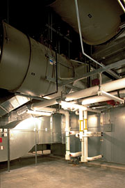
Variable-volume, single zone air-handling systems with CO2 level occupancy sensing. For the Worship Center, twin 40,000-cfm single zone, variable-volume AHUs were installed. The primary supply mains out of each AHU are routed through two large (approximately 12-ft by 6-ft by 18-ft) acoustic plenums before penetrating the walls from the fan rooms into the auditorium.
Within the fan rooms, each unit has two duct-mounted reheat coils: one for the stage and choir loft, the other for the main worship space. Since all of the spaces are open to one another, they are basically the same thermal zone. Separating the reheat coils, however, allows the thermostat on the stage to be set at a lower temperature than the seating area to allow for comfort under hot stage lights.
Since there can be a wide swing of attendance from service to service, using a typical constant volume system for the auditorium could have resulted in a significant waste of energy.
Instead, the supply and return fans for both units have VFDs to modulate the system supply and return air volume delivered to the auditorium.
Additionally, carbon dioxide sensors in the primary return ducts at the back of the auditorium control the amount of outside air delivered to the space. During periods of low internal load, typically coincident with low occupancy, the amount of outside air required to be supplied to the worship space decreases.
During these periods, significant energy savings can be realized by limiting the amount of outdoor air that must be conditioned. Since the space is likely unoccupied or sparsely occupied for large periods of time, the CO2 sensors will signal the outside air dampers to close to their unoccupied minimum setting. This will reduce the heating or cooling energy required to maintain the indoor conditions for the Worship Center significantly.
Tandem AHUs that operate as one. For the spaces around the periphery of the building (such as the offices and classrooms), engineers employed a different system of airside load staging. The AHUs are arranged in matched pairs that are connected together in common supply and return plenums. There are separate supply and return fans for each AHU, which are controlled individually based on static pressure and fan tracking.
During full load periods, the VSDs on all four fans for each AHU pair were designed to run at full speed. During low load periods, however, one of the AHUs (and therefore two fans) from each tandem pair was designed to shut down completely with the entire load being met by the second unit. This allows for a significantly higher total turndown ratio for the systems, and allows the fans to be running at better efficiency for low load situations. Again, since the bulk of the year is spent at part load conditions, designing this flexibility into the systems will result in potentially significant energy savings for the owner.
Centralized hot and chilled water system efficiency. Similar to the concept of using multiple AHUs, both the hot and chilled water generation systems were designed with load staging controls. At full load, either both boilers or both chillers were designed to run at full capacity. During low heating or cooling load periods, respectively, one of the boilers or chillers was designed to go offline to keep the second unit running as close to its peak efficiency as possible. Furthering this concept, the chilled water system was designed with variable-speed primary pumps to save on pump energy during low load periods.
Lighting efficiency. The lighting systems have been designed so that the theatrical lighting system never operates beyond 95% maximum output, thus increasing the useful life of the lamps. The house lighting system operates in similar fashion and is fully integrated with the operation of the theatrical system. These systems are then coordinated with the remainder of the facility to allow centralized control for energy efficient operation.
The general lighting systems throughout the facility have been designed to utilize a centralized control scenario that allows zones of the building to be controlled for after hours sweeps and on/off control. This accommodates an energy control operation for turning off the lighting in unused areas of the building and guaranteeing the operational efficiency discussed with the owner.
The system is utilized for the classrooms, meeting rooms, restrooms, and nursery areas in conjunction with occupancy sensors and strategically placed manual override switches. The system is also utilized to control all corridor lighting and exterior lighting. This allows for the centralized control of these general lighting areas via manual operation or programmed setpoints.
In providing this level of control automation, the system maximizes the operational efficiencies of the lighting systems. The lighting control scenario also utilizes preset control systems for areas such as the choir room, the guest reception areas, and the commons area to gain greater flexibility in these areas while not compromising the efficiency of the operation.
These control systems are also connected to the zone sweep system and are set to control the maximum amount of energy consumed during their operation. This is coordinated with the BAS and EMS for a coordinated approach to the control of building operations.
Future Expansion of the Hot Water Plant
Since the construction involved in this project was only Phase 1 of a potential four-phase campus expansion program, provisions for the future expansion were made in the design of the central hot water system.
At present, two boilers were installed, but there is space in the boiler room for an additional boiler to be installed and brought online as the Grace Church campus expands. This strategy will allow the owner to have centralized generation capabilities for one of the main mechanical systems in the campus, which, among other things, will help reduce maintenance costs.
Service Entrance and Transformer Design for Expansion
The design of the service entrance equipment and the distribution system allows for future growth of the facility. The service entrance equipment employs an underground transformer vault that is sized to accommodate three transformers for service.
The future load requirements of the campus will require three service transformers but the present load can be accommodated with two. The vault is configured with a service bus arrangement that allows the addition of the third transformer and also contains bus links between the three bus sections. This allows for full growth flexibility and expansion without disconnecting power to the facility. The arrangement also increases the operating efficiency of the equipment that maximizes the owners demand charge efficiency.
Integrated Design Approach
The design of any religious facility involves an approach to design that attempts to maximize the use of the capital investment while incorporating the elements of inherent flexibility. Grace Church is a model for cost-effective design for the large new churches that are now being built throughout the country.The basic engineering design goal was integration of all building systems throughout the planning process — not only integration within each discipline, but across the design of the entire building. At Grace Church, great measures were taken to ensure that not only did the individual systems and features met their desired design goal, but that they worked well together for the building as a whole.
Also of great importance is that the owner’s needs are met. One of those needs, fundamentally, is the project budget. Grace Church opened on time and on budget.
Additionally, Grace Church was awarded a Grand Award from the American Council of Engineering Companies for Minnesota in January 2003. ES


