
The building relies on the central plant in Abbott's campus-like headquarters for all its utilities including chilled water and steam. Therefore, there is only secondary chilled water distribution system in the building.
Over the years, the chilled water load for the building has steadily increased due to the addition of various AHUs, resulting in a shortage of chilled water supply as the secondary distribution system runs out of capacity.
The existing secondary pumping system consists of two base-mounted centrifugal pumps, each handling 660 gpm at 100 ft of total head. The total capacity of the pumps is 1,320 gpm at 100 ft. However, the projected chilled water load for the building is around 2,400 gpm at the peak of summer. It is obvious that the chilled water distribution system in this building needs to be upgraded.
Challenges
However, to upgrade the system is much more than simply replacing the existing secondary pumps with larger ones. The complex distribution piping system also needs to be upgraded in order to handle significantly increased water flows. Unfortunately, this presented a serious challenge to the engineers who took charge of this project.First, the chilled water piping is an integral part of the building piping system which includes steam and condensate, process water, distilled water, compressed air, nitrogen, and many others. A major replacement of the chilled water supply and return pipes would involve the rerouting of various pipes and it would take at least a month to complete. In other words, the facility would have to be shut down for an extended period for this project. Considering all the manufacturing activities going on in this vital building, it was quite impossible to have a shutdown last more than three or four days.
Second, the cost associated with a major piping replacement was way more than the management was willing to spend. Particularly when the project has to be executed within a short period of time, it means a great share of premium time would have to be paid to contractors, which would drive the cost even higher.
Facing this challenge, Abbott Engineers and their consulting engineer from Washington Group, worked closely together to come up with an ingenious solution that minimizes piping system replacement: turning a traditional chilled water distribution system into a circular loop.
Past Solutions
Figure 1 is a schematic of the original chilled water distribution system in Bldg AP16. The distribution piping consists of two loops: east and west. As is shown on the figure, the east loop is much longer than the west loop and also has much more chilled water coils hooked up to it. This directly leads to system unbalance: Many coils on the far end of the east loop were often starved of chilled water while a few air handlers on the west loop were experiencing overcooling.The past solution to this off-balance problem is to rely on the individual balancing valves on the west loop to induce high-pressure drops in order to limit chilled water flooding into these west loop coils. This in turn leads to the higher overall head for the chilled water distribution system, further straining the system capacity.
Other consulting engineers in the past had proposed reverse return loops as shown on Figure 2 as a solution to this off-balance problem. This solution is impractical and costly. To install reverse return piping for so many coils is so extensive that the cost would be all but prohibitive. Besides, it does not improve the condition at all. The reverse return concept is basically to use the extra piping to balance pressure drops between nearby and faraway coils. The idea is that the closest coil has the shortest supply piping and the longest return piping while the farthest coil has the opposite. So overall, each coil has approximately the same pressure drop. This type of balance is actually already accomplished by the use of a balancing valve in each coil piping loop. The farthest coil has a wide-open balancing valve while the closest coil has a half-closed balancing valve that creates a pressure drop equivalent to that over a long pipe.
New Loop Concept
In the hvacr community, the term "loop" has been widely used: a chilled water loop, a steam supply loop, etc. In reality, few facilities are really using a loop. Most of the so-called loops are basically a pair of distribution pipes consisting of a supply line and a return line. These lines start from a central power plant and end at the farthest point of use. They become a "loop" because the utility fluid (such as chilled water) returns from a return line back to the power plant.A new "loop" concept was developed for this project and is illustrated in Figure 3.
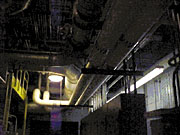
This conceptual design links the east loop together with the west loop, thus making the chilled water distribution system a true "circular loop." Using this design, most of the existing chilled water piping was left untouched. Only some 500 ft of new piping was installed to bridge the two loops together. Part of this new piping is shown in Figure 4.
This innovative design accomplishes the following:
- Saves the project costs of 525%;
- Shortens the system shutdown from two months to four days; and
- Achieves system self-balance.
First, the cost savings are obvious. This innovative design avoided the originally planned wholesale piping replacement, thus cutting the project cost from the initially estimated $2.5 million to $400,000.
This tremendous savings fades in comparison with the second benefit, which is the greatly shortened shutdown schedule. With the original plan, the chilled water distribution system would have to be shut down during the construction period, which in turn would shut down the facility production. With this innovative design, the bridging piping system could be installed while the existing piping system was operational. A very short shutdown was required only for the chilled water pumps replacement and the bridging piping tie into the existing system. With a daily production valued at a few million dollars a day, the benefit of this innovative design is immeasurable.
The third benefit is the key of this innovative design and will be elaborated in the following.
Self-Balancing
This new chilled water loop is not really a loop. In other words, the chilled water does not flow from the east and return to the west or vice versa. Instead, the chilled water flows from both the east and the west lines simultaneously and stops at a moving neutral point.This moving neutral point is the key. For example, in the past, coil 11 is the farthest coil in the east loop and was always supplied from that loop. During peak demand periods, this coil was more often than not starved of chilled water supply. With this new design, this coil is most of the time supplied from the west loop. But not always. During periods when demands from coils 12 through 15 are greater than those from coils 1 through 10, coil 11 is supplied from the east line, thus moving the neutral point from between coils 8 and 9 to coils 11 and 12. This moving neutral point enables the farthest coil to pick its chilled water supply from the least-resistant route. Also note that the "farthest coil" also changes depending on individual coil loads. Examples shown on Table 1 and 2 clearly illustrate this point.
Obviously, the neutral point for Table 1 is between coil 8 and 9. As the demands change as in Table 2, the neutral point changes as well.
Now, the supply of coil 9 is no longer from the west loop. It comes from the east route as the east route's demands decrease while the west route's demands increase. Although these abrupt demand changes may not be common for commercial buildings, it is quite typical for industrial plants where many chilled water coils are for process usage and their demand can be on and off, depending on whether or not process equipment is operating.
Basic Design and Sequence of Operation
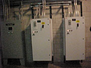
Two Armstrong base-mounted centrifugal pumps are designed for the secondary circular loop that bridges the east and west loops. Both pumps are installed with a variable-frequency drive (vfd).The system is controlled by a Modicon PLC using a Factory-Link monitoring system. The vfd's and the control panel are shown in Figure 5.
The two pumps are designed to work as a lead/lag alternating single pump except when high chilled water demand requires that the resting pump be brought on-line to assist. The system must then switch to a balanced parallel pumping system. When the load decreases, the system reverts back to a single pump setup.
A pressure transmitter is installed at both east and west legs about 2/3 of the distance from the pumps to the farthest coil. The pressure was set at 65 psig. The lower pressure reading of the two will modulate the pump speed to satisfy load demands.
Problem Solved
The new chilled water distribution system has been operating since January 2000. Significant energy savings, higher operating efficiency, and tighter controls of space temperature and humidity have been achieved. A comparison between 1999 and 2000 operating data is shown in Table 3.
This data clearly indicate that the new system is much better balanced as the system pressure drops more than 40% from 110 psig to 65 psig. Instead of relying on balancing valves to create high pressure drop in one loop in order to force chilled water to flow to the other loop, this circular system balances itself out, bringing the system pressure down, thus realizing almost 80% pumping energy savings.


