
The package boiler and burner market is evolving to adapt to new environmental regulations. Current environmental regulation trends strive for lower NOx and carbon monoxide (CO) emissions from fired package equipment. As a result, older boilers are either replaced with new package boilers or retrofitted to install new low-NOx burners (LNB) or ultra-low-NOx burners (ULNB). Whether a facility chooses to replace existing boilers or burners to comply with new environmental regulations, end users must consider the construction of the boiler to ensure the CO emission requirements can be achieved.
Understanding CO Bypass
Generally, end-users link achieving CO emission requirements with burner performance. However, boiler construction is equally vital to ensuring CO emission compliance. A typical burner application will either use a solid, liquid, or gaseous hydrocarbon as the primary fuel for combustion. When the combustion reaction takes place, the burner mixes air and hydrocarbon fuel. As a result, the carbon from the fuel will react and oxidize with the oxygen in the air. The oxidation reaction causes the carbon to oxidize to CO and then further oxidize to CO2 — one of the final byproducts of complete hydrocarbon combustion.
The combustion reaction requires both sustained temperature and time to ensure complete combustion. The volume where the combustion process takes place must sustain a minimum temperature of 1,375°F or higher to ensure the total thermal destruction of CO. The required residence time is defined as the amount of time within the reaction zone needed to complete the chemical reaction processes, which depends on both the fuel constituency and the temperature of the combustion reaction zone. A boiler’s combustion zone is located in the portion of the furnace prior to entering the boiler convective heat recovery section, at the furnace exit.
LNB and ULNB are designed to minimize the peak flame temperature and lower the thermal NOx produced during the combustion reaction. Most LNBs and ULNBs achieve these results by staging fuel and air down the length of the furnace to increase the volume in which the combustion reaction takes place. In doing so, the staging reduces the overall peak flame temperature and lowers the amount of thermal NOx produced. The utilization of a larger combustion volume, which is rich in incomplete combustion products, means boiler construction becomes more critical in ensuring low CO emissions. A boiler that does not have a completely sealed furnace is likely to exhibit CO bypassing or short-circuiting. CO bypassing occurs when the CO produced in the oxidation reaction prematurely exits the combustion zone via voids in the division wall before completing the oxidation reaction. The pressure differential across the voids in the division wall allows for partially oxidized byproducts of the combustion process to flow into the generating section of the boiler and then exit through the breaching of the boiler without allowing enough time and/or temperature to ensure the reaction has completely taken place.
Engineers should consider CO bypass when retrofitting a burner with a tight, compact flame to an LNB or ULNB design, even if elevated CO emissions are not observed with an existing design. LNB or ULNB are designed to produce a flame that utilizes the majority of the available furnace volume, which positions the intermediate combustion products closer to the furnace walls. By positioning the combustion products closer to the walls, there is a higher probability that the combustion products will pass through any voids in the wall.
Common Areas for CO Bypass
CO bypass may also occur in cracked mud drum or steam drum seals. Failing refractory that has begun to pull away from the boiler pressure parts creates small gaps large enough to allow flue gas bypassing to occur.
Tangent tube division wall construction is practically guaranteed to allow bypass to occur, as there is an unsealed gap between each tube that runs the height of the furnace. Even though the tangent tubes may not have a visible gap, the adjoining tubes do not form a gas-tight seal.
Voids in the division wall construction can sometimes be challenging to detect. For example, certain types of refractory have a detrimental characteristic whereby the refractory contracts at elevated temperatures. Once the furnace reaches elevated operating temperatures, the refractory contracts and pulls away from the tubes, voiding the gas-tight seal. When the boiler goes offline, the refractory cools and expands back to as-applied dimensions. At normal ambient conditions, this gap is not detectable.
Boiler construction, dating back several decades, employed refractory front wall designs that were not gas-tight, which allowed for combustion gases laden with CO to exit through the breaching of the boiler. Gas bypassing through the front wall seal is prevalent in A- and O-type boilers, where the breaching of the boiler is directly over the burner centerline.
Boilers that have undergone modification to seal weld the tangent tube division walls in order to mimic a membrane-style wall can exhibit bypassing if the refractory drum seals were not replaced. This is because the seal weld on the tubes must extend down and into the refractory seal to ensure that the combustion chamber is sealed.
Most new package boilers available today have division walls with membrane tube construction. Membrane tube walls are constructed by seal welding a metal strip between each adjoining tube. A metal strip (the membrane) extends down and into the drum crotch seal, forming a gas-tight division wall. Some package boiler OEMs offer a watertube front wall construction, which is advantageous to preventing bypassing. The watertube front wall is physically joined and seal-welded to the division wall on these boilers, ensuring no voids for bypassing occur between the two adjoining walls.
Furnace Construction Example: D Style Boiler
To illustrate this problem, a typical D-style package boiler is shown in Figure 1.
In modern package boilers, the furnace enclosure is typically built of welded membrane tube construction. A membrane is welded to each adjacent tube to form a seal, as shown in Figure 2.

In many older package boiler designs, the division wall that separates the furnace from the backpass of the boiler (which contains the superheaters and boiler bank) is composed of tangent tube construction, as shown in Figure 3.
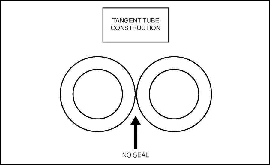
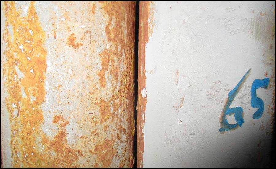
Figure 4 shows a tangent tube in a division wall of a D-style boiler. Since there is no welding or positive seal between the tubes, a significant amount of space for bypassing flue gas from the furnace to the boiler backpass is available.
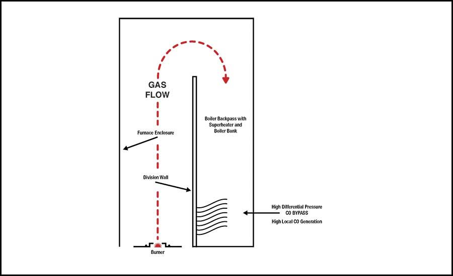
Package boilers are typically built of a pressurized design with no induced draft fan installed. The forced draft fan pressurizes the furnace and conveys the flue gases to the stack exit.
High carbon monoxide (CO) quantities are formed in close proximity to the burner zone during low-NOx firing. This CO formation zone, in combination with the high differential pressure between the furnace and the backpass, can result in the bypassing of CO through the spaces between the tangent tubes and into the boiler backpass. The temperature in the backpass of the boiler at the point of bypassing is below the required temperature to promote further combustion of CO, so the reaction ends, and the high CO level is established.
Although the CO measured at the exit of the furnace may meet the specified requirements, some installations have had such bypassing of these furnace gases laden with CO exit to the stack — failing stack emissions tests. With permit levels typically very low, any bypassing of the CO pollutant becomes a significant risk to achieving the permitted level. Inspection of the furnace division wall and the installation of rods to close any gaps found in the division wall to prevent bypassing of carbon monoxide to the stack has effectively prevented this condition.
Diagnosing and Evaluating CO Bypass
Diagnosing and testing for CO bypassing becomes critical when determining the root cause of elevated CO emissions. Typically, the first indication of CO bypassing becomes evident when combustion tuning is being carried out on the unit. The burner will exhibit CO emissions that are uncharacteristically high for the burner. A trained combustion service engineer will vary the fuel staging, excess air rates, and flue gas recirculation rates on the burner to mitigate the elevated CO. If the CO emissions remain largely unchanged, even after considerable changes in the tuning parameters, bypass is the likely cause of the high emissions.
To accurately diagnose CO bypassing, the flue gas at the back of the furnace — near the entrance to the generating section of the boiler — needs to be sampled. The flue gas at the back of the furnace will travel the entire length of the furnace and undergo the designed amount of time and temperature necessary to complete the combustion reaction. If the flue gas sampled at the rear of the furnace has low or no levels of CO, then bypassing is the likely root cause of the elevated CO emissions in the stack. Some of the incomplete combustion gases laden with CO will pass through a gap or hole in the division wall before reaching the end of the division wall/back of the furnace, resulting in high CO content in the stack gas.
There are several safe ways to sample flue gas from the back of the furnace. A simple way to sample flue gas is to temporarily disconnect the cooling air from the rear sight glass and pull a sample from this port. Another simple method is to find an existing tap, either on the back wall of the furnace or near the division wall, and insert a water-cooled probe to sample the flue gas. All samples pulled from the rear of the furnace should first pass through a condensing coil or bubbler to cool the sample to prevent damage to the emission analyzer. Flue gas pulled directly from the rear of the furnace will damage any emission analyzer without proper cooling.
Once the flue gas has been sampled from the rear of the furnace, the results of the sampling will need to be validated. A sample of the emissions from the stack should be drawn at the same time as the sampling at the rear of the furnace. When the two samples are compared, the oxygen and NOx levels of the samples should be similar, and the CO emissions should be significantly different. A confirmation of bypassing will show little to no CO in the rear of the furnace, while the stack sample should show elevated levels of CO.
After diagnosing the root cause of the elevated CO emissions as bypassing, the furnace will need to be inspected for voids where the bypassing occurs. CO emissions in the stack will remain elevated until the voids are eliminated.
In summary, compliance with new environmental emission requirements is not solely based on proper burner operation; it requires a holistic approach of looking at the entire fired equipment package. The construction techniques and materials used in boiler construction require attention to ensure the furnace is entirely gas-tight to help ensure proper CO emissions are achieved. The evaluation of a boiler’s construction is critical when older boilers are updated with new ULB and ULNB to provide a successful retrofit project that meets all environmental goals and regulations.


