
What makes gas turbines lose performance? This is an interesting question that many people will try to answer given their own theories and experiences. The reason for this is quite simple: Gas turbines literally operate all over the world, from deserts to Artic research stations to tropical zones to heavy industrial areas, and each location comes with its own performance challenges. This article will address the performance of gas turbines with a special emphasis on the challenges facing operators in the Middle East region as well as the filter types and the relevant filtration processes utilized in land-based gas turbines.
The Importance of Gas Turbine Performance Assessments
Many questions come to mind when the topic of gas turbines is addressed. Some of these questions include: Why is assessing gas turbine performance critically important, and how is performance defined in relation to the operation of a gas turbine?
The performance deterioration of industrial gas turbines has been studied since 1914, when the ideal cycle of Brayton was modified to represent real conditions[1]. At the end of the 1940s, it was observed that gas turbine deterioration affected the power production and increased the fuel consumption.[2] The increases in the fuel price in the 1970s obliged gas turbine users to look at new ways to reduce the costs of operation. During this period, the deterioration mechanisms that affect engine performance were classified.[3]
The expansion of industrial gas turbines in the 1980s and the installation of combined cycle power plants (see Figure 1) resulted in new technologies, and at the end of this decade, increases in the engine efficiency to 42% were seen.[4]
Today, OEMs claim gas turbines can operate with efficiencies of 45%; however, these results are adjusted back to ISO conditions, namely 15°C and 1 Bar pressure, so that figure of 45% will be reduced when looking at performance in very hot climates. The performance of all gas turbines is affected through their actual operation because the air being ingested contains millions of airborne particles that affect the performance in a variety of ways.
One of the most readily available indicators of losses in gas turbine performance is a drop in power output, either mechanical or electrical, depending upon the installation, although this can sometimes be overlooked — especially if the gas turbine is not operating at part-load conditions or at base load. This is because, when at part-load, a gas turbine has a degree of flexibility within the operating parameters and limitations to meet the demand placed upon it by increasing the fuel flow or permitting a higher exhaust gas temperature to suit the situation. Whilst this allows the gas turbine to continue to operate, the full repercussions of the degraded performance may not become apparent until weeks or even months later at the next service outage. An alternative method, one that requires calculations as reported by operators, is that of compressor efficiency; however, this does have its limitations. Firstly, the range of compressor efficiency is relatively small, and, therefore, any variations — both good and bad — are also smaller and harder to detect; secondly, and perhaps more importantly, is the fact that once identified and quantified as a percentage, these benefits or losses cannot be used to provide a monetary value.

FIGURE 1: The operation of a combined cycle system for a power generation application.
All Images courtesy of the authors


FIGURE 2a & 2b: Sandstorms remain a challenge when it comes to filtration selections and standards.
What Is Compressor Fouling?
A well-recognized challenge of gas turbine operation is that of compressor fouling. It occurs when contaminants deposit on the compressor blades as a result of exposure to abrasive environmental conditions. The result is a reduction in mass flow rate and pressure ratio, which leads to a reduction in compressor efficiency. If power output is to be maintained, additional fuel must be burned, resulting in higher firing temperatures in the turbine section and other well-known associated issues. Several researchers have stated that 70%-85% of gas turbine performance degradation is due to compressor fouling. Therefore, particle deposition emerges as a critical problem to the compressor assembly. To engineer an appropriate solution to this particular challenge, experts should ensure that atmospheric airborne particles, as shown in Figure 2, are characterized both physically and chemically and that appropriate filter selections are made. This would facilitate a good starting point for decisions to be made about how to better tackle many critical parameters, such as particle concertation and size distribution.
Compressor fouling is a consequence of the operation and the fact that gas turbines need to ingest air to operate and that air will contain millions of small particles. Some of the very fine particles may find their way through the filtration stages or even through leaks in the filter housing itself. Needless to say, particles will find their way into the compressor and likely attach themselves to the compressor blades or casing. The result is that the swallowing capacity of the compressor will be reduced, and the efficiency will be affected as the engine is choked. To achieve the rated output of the engine in this situation would result in additional fuel being burned, which would have a negative outcome. First, the exhaust gas temperature will increase as a consequence of the additional fuel, which will have a significant impact on the life of the turbine section. Secondly, the cost of operation will increase as more fuel will be burned than would be necessary, and, thirdly, and worst of all, the emissions will increase. For these reasons, it is good practice to prevent as many particles as possible from entering the compressor; and for the ones that do enter, a good compressor washing regime should be set in place.
The type of filtration selections used in the gas turbine operations is the first aspect to be investigated, and their use is analyzed in much greater detail than previously produced articles, together with a review of compressor washing options.
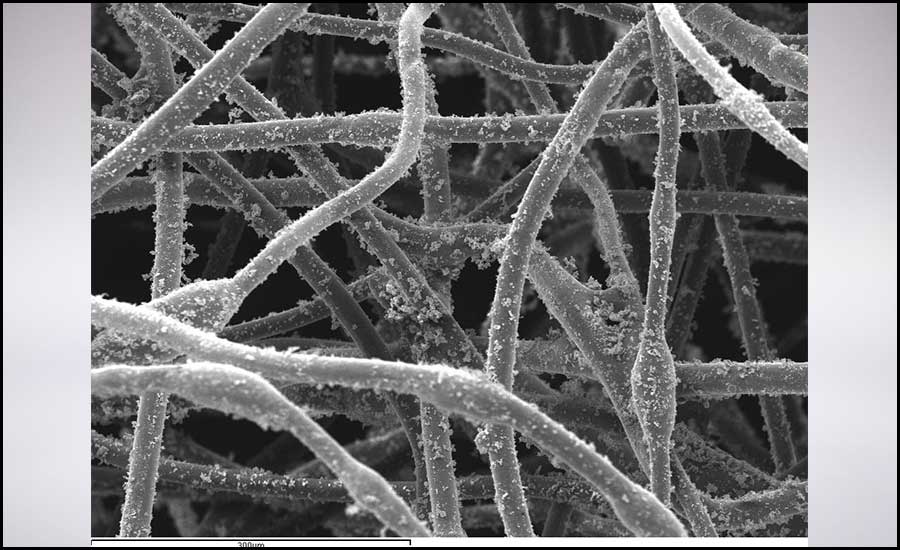
FIGURE 3: A scanning electron microscopic image of dust-loaded filter media in the stationary stage.
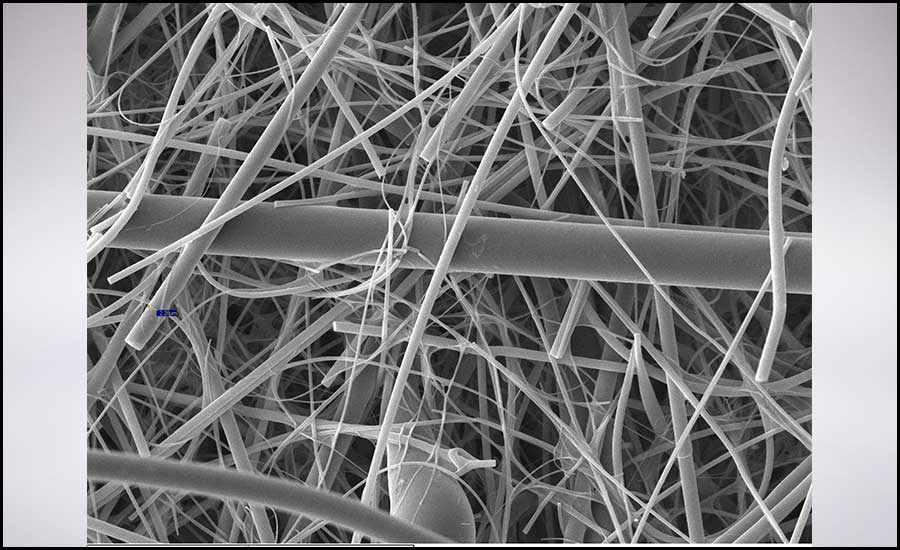
FIGURE 4: A scanning electron microscopic image illustrating filter media inhomogeneity.

FIGURE 5: Scanning electron microscopic images showing dendrite formation on filter media.
Air Filtration for Land-Based Gas Turbines
In land-based gas turbine operations, atmospheric air passes through a filtration housing prior to entering the compressor assembly. The filtered air is then compressed to a high pressure and temperature before entering the combustion chamber where fuel is added and combustion occurs at constant pressure. The gases that leave the combustors are very hot with a large amount of energy, which is converted to work in the turbine, part of which drives the compressor, and the reminder drives the generator to produce power.
Since gas turbine operations require enormous amounts of air, the role that air filters play to separate and capture unwanted contaminants becomes well-pronounced. Ultimately, the required air quality is attained by means of employing appropriate air filters that correspond to the performance of the gas turbine engine. Conventionally, filter efficiency increase is associated with a rise in pressure drop notwithstanding the pressure drop occurring as a result of particle loading. In the Sahara Desert and the Arabian Peninsula, filter installations in land-based gas turbines are subjected to humid air and high dust concentration. As a result, filter performance both deviates from that predicted by filter manufacturers on one hand and degrades when excessively overloaded with particles at higher concentrations than dictated by international filtration standards on the other hand. Therefore, this can both mislead the concerned engineer selecting air filters and contribute to the gas turbine performance degradation.
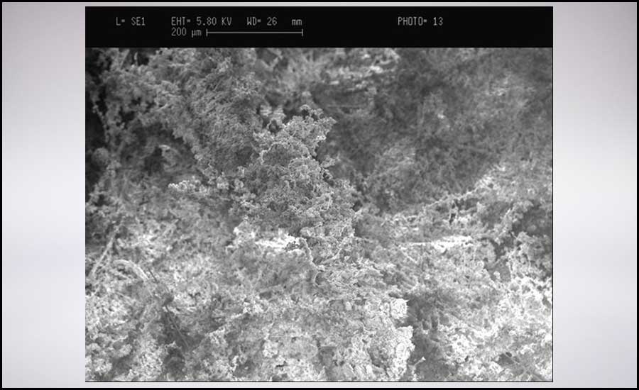
FIGURE 6: Surface deposition on depth filter media in the absence of no or poor pre-filtration employment.
The Utilization of Air Filters in Land-Based Gas Turbines
The inlet filtration systems of gas turbines use surface (pulse) filters, depth (static) filters, or sometimes a combination of both.
Pulse filters are classified as surface filters where particles are expected to settle on the surface, and the dust layer formed on the surface of the filter medium does most of the filtration action. In surface filtration, the characteristics of the particles and geographic location influence the particle deposition on the filter medium. On the other hand, static filters are depth filters, where the filtration is intended to take place within the depth of the filter medium, i.e., particles are deposited around the fiber while keeping the pores clear/open. This stage of the depth filtration is regarded as “stationary,” as the rise of the pressure drop is negligible (see Figure 3). As particles continue to deposit on the filter medium depth, the aerodynamics of the flow around the pore changes as pores are reducing in diameter and particle count increases. Particle bridging and the clogging of filters is dependent on several parameters, including particle concentration, size distribution, and their correlation with pore size distribution. Concomitantly, a filter’s pressure drop continues to increase as a result of dust cake formation on its surface. This acts as an additional layer of filtration until the recommended final pressure drop by the manufacturer is reached for replacement.
Air Filter Media
The building block of air filters is the porous media. Perhaps the most critical challenge when addressing filter performance is the inhomogenous nature of filter media (see Figure 4). Filtration media inhomogeneity creates non-uniformity in the gas flow and affects filter performance. On the other hand, in the absence of appropriate filter selection and installation, filter loading conditions change, and, therefore, performance deviation is imminent.
Furthermore, dust storms are another challenge as they increase the particle concentration in the air and affect the dust loading of air filters. Evaluated dust concentration can cause particle bridging, and the formation of dendrites on the surface of the depth filters impair them from acting as depth filters (see Figures 5 and 6). To better understand particle deposition in air filters for land-based gas turbine applications, a good start would be to address different filtration processes of particle deposition on or within the filter medium.
Filtration Processes
The first step in the general understanding of the air filtration process is distinguishing between the two types of filtration processes, namely depth and surface filtration. The main difference between both processes lies in the location of deposited particles on the surface or within the filter medium. Fabric and membrane filters are considered surface filters, while fibrous and granular filters fall under the depth filtration category.
Surface Filtration — In surface filtration, large particles are expected to be deposited on the surface of the filter medium by a sieving mechanism so as to form the so-called dust cake (see Figure 7). Thus, surface filters rely on the formation of the dust cake to effect most of the filtration action and, therefore, have a high pressure drop. Pressure drop is the measure of airflow resistance through a filter. In this process, the dust cake layer itself becomes the main filtration segment of the entire filtration process. A detailed knowledge of the properties of the local atmospheric dust is needed to better evaluate the surface filtration process. Pulse filters are a good example of surface filters and are generally used in land-based gas turbines.
Depth Filtration — Depth filtration relies on capturing the particles within the filter medium (see Figure 7). This method of non-cake filtration requires an understanding of the media properties. The depth filtration process allows fibrous filters to have the same or a better degree of purification and minimal resistance as that of surface filters. In this process, fibrous media is used extensively due to its low pressure drop properties and better performance at high temperatures. The structure of fibrous media is delicate and may not be regenerated either by washing with water and/or through the use of compressed air. Attempting to regenerate a fibrous filter by ejecting the dust out of it will lead to the destruction of the structure of the media, and the dust particles may not be removed completely. The porosity of fibrous filters is around 90%, which indicates the sieving mechanism plays no significant role in the process. Figures 7 and 8 illustrate the comparison between surface and depth filtration processes and provides a sample installation of static and pulse filter in land-based gas turbines, respectively.
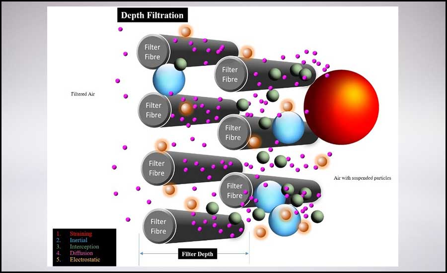
FIGURE 7: A comparison between surface and depth filtration processes.


FIGURE 8a & 8b: A sample installation of static (right) and pulse filter (left) in land-based gas turbines.
Depth filters can be utilized for the pre-filtration stage(s), as they are capable of reducing the concentration and size distribution of the airborne particles prior to reaching final filters. Dust-loaded HEPA filter installation with and without pre-filtration are shown in Figure 9, where a HEPA filter[11] preceded by a Fine filter[12] is loaded with less particle size distribution and concentration.


FIGURE 9a & 9b: A HEPA V-bank cartridge installed without pre-filtration (left), and the same filter with a pre-filter (right).
Flow-Through Pleated Media
Pleated filters are commonly used in land-based gas turbines as opposed to flat filters. It is assumed when considering flow through a pleated filter that the fluid is homogeneous, the filter media is porous, and there is no interaction between the fluid and the filter media. As shown in Figure 10, the surface area of a pleated filter Ap is greater than that of a flat filter at a given frontal/face area. Therefore, the face velocity of a flat filter, Vf is greater than that of the pleated filter. As a result, the residence time of particles within the pleated filter media (Tp) is longer when compared to a flat filter residence time (Tf).
Pleating filter media provides a larger surface area in a given space (see Figure 10), which decreases the air medium velocity. Filter efficiency increases as a result of slower air medium velocity, as it extends the residence time of particles within the filtration media. Consequently, the probability of the particle-fiber contact is enhanced, and a hike in the diffusional capture efficiency is experienced by the per unit area of the filter when compared with a flat sheet medium.
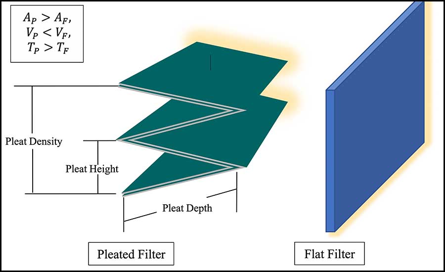
FIGURE 10: A comparison between pleated and flat sheet filter media at the same given space.
Pleating filtration media enables an increase in the collection efficiency for a given pressure drop. However, excessive pleating can be counterproductive due to fluid viscous drag in the pleat spacing, which can increase with over-pleating. Clearly, there are two competing effects to the overall pressure drop of the filter.
Furthermore, it is assumed that the flow rate is kept relatively low, and the pleat geometry is rigid. In terms of structural integrity, pleated medium panels tend to be more stable than a flat sheet of the same medium, which is inclined to deform and eventually rupture. However, that neither rules out any panel deformation in pleated filters nor pleat-crowding and/or ballooning.
The pressure drop through the pleats is generated by:
- The alterations in the cross-sectional area as the air flows into and out of the pleat;
- Filter media thickness;
- Flow contraction and expansion in the upstream and downstream regions, respectively; and
- Viscous drag between the fluid and porous surface on both the upstream and downstream channels.
One cannot address the issue of a filter’s pressure drop without considering the permeability reduction experienced by the filter media with and without particle-loading. At a low pleat density, the pressure drop increases due to reduced surface area and increased media face velocity. On the other hand, at high pleat density, pressure drop increases due to increased viscous drag in the pleat spacing.
Ultimately, a reduction of air filter permeability as a result of media deformation and pleat ballooning should be of a major concern to the operators. Furthermore, emphasis must be placed on the correlation between the pleats physical properties, fluid flow rate, pressure drop, and overall filter efficiency to better understand filter performance and appropriately select filters for each corresponding application. Inappropriate filter selection, installation, and maintenance can lead to filter failure through pleated panel deformation, media rupture, disintegration of filter media from the filter cartridge, or a combination of thereof (see Figure 11).
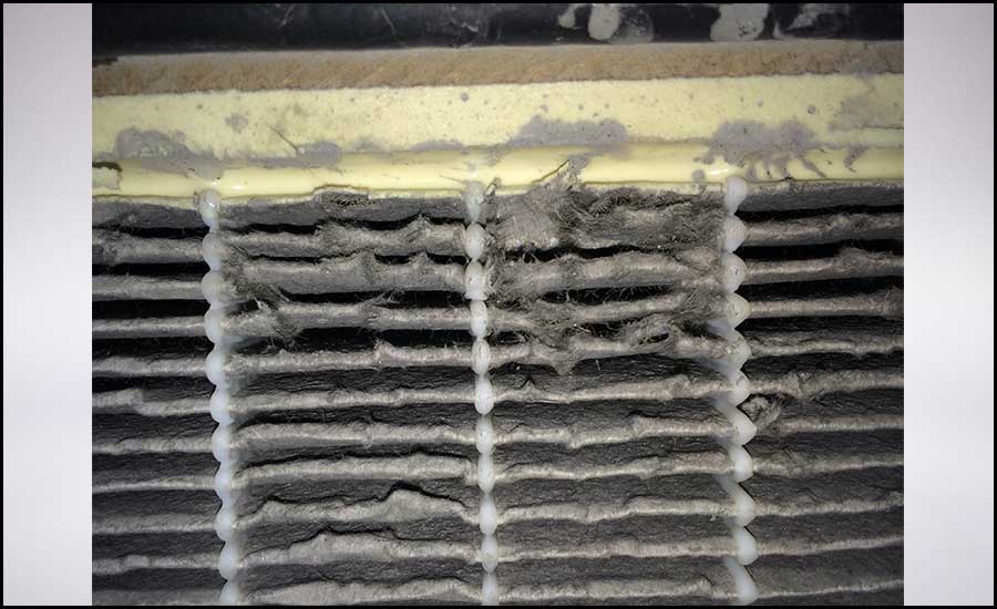
FIGURE 11: Ruptured and deformed filter pleats during particle loading.
The Performance Degradation Problem
It is now possible to characterize the filter along with the pros and cons of the different designs. However, it is well known that the Middle East faces unique issues associated with its location. Firstly, gas turbines are operated in very high ambient temperatures. Figure 12 illustrates temperatures approaching 40°C in the months of July and August, and peak temperatures can be as high as 50°. These temperatures will quite literally destroy the performance of a gas turbine, which has a rated output that will have been quoted at 15°.
Secondly, the regular presence of sandstorms that can last for days at a time and their aftermath, which can take even longer to dissipate, illustrates the challenges presented to the operators of gas turbines in the region.
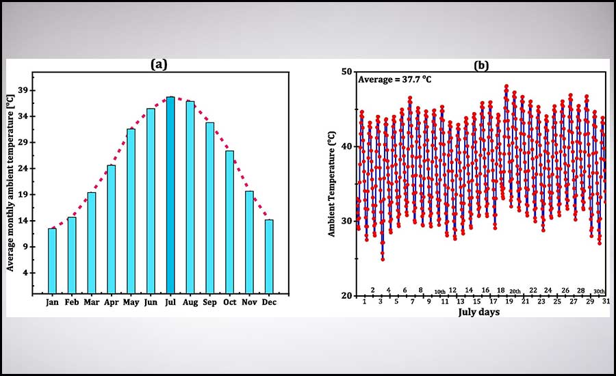
FIGURE 12: The ambient temperature for Kuwait City (29.37◦ N, 47.97◦ E).[16]
Performance Recovery
In terms of performance recovery in these situations, a number of steps can be taken at various levels of disruption and cost. A starting point might be, once again, to consider filter design in terms of what is required of the environment. Initially, we can ask ourselves some questions as to the function of the filter. Yes, the filter is required to capture particles, but it must also deliver a certain amount of air per second to meet the needs of the gas turbine. This presents a problem from the start when the environment is so changeable. A filter that can capture and retain moderate atmospheric contaminants with different types, concentrations, and size distributions will soon become clogged if further challenged by a sandstorm. Equally, for air filters to confront a sandstorm, several stages may be required to efficiently separate suspended debris from the airstream. However, that does not necessarily warrant the complete capture of PM1 to ensure they do not reach the compressor assembly.
In situations where particles enter the compressor section, there is always the option to perform an online or offline compressor wash. This can be done with either demineralized water or with the addition of some cleaning detergent. The more modern compressor wash systems will allow the operation to be carried out while the gas turbine is still operating, i.e., online. It should, however, be noted that this method relies on a special cleaning product that keeps any fouling removed from the early compressor stages in a fluid state until it reaches the combustors, where it is incinerated. If only demineralized water is used, the fouling from the early stages is merely moved further into the compressor section. This will initially show itself as a slight improvement in performance but could have other impacts after continuous running periods.
If air temperature and density are considered alongside the average daily temperatures in Kuwait, for instance, it can be seen that the performance of the gas turbine will be reduced by as much as 35% from its rated output at ISO conditions (see Figures 12 and 13). Perhaps the gas turbine was specified to compensate for this, namely the purchase of a higher rated unit on the understanding it will underperform. That may have been acceptable 20 years ago, but there is now a duty of care to use fossil fuels responsibly and reduce excessive emissions and waste fuel.
An alternative to over-specifying a gas turbine is to change the inlet conditions, which is the air temperature that is delivered into the compressor. This can be done in a number of ways through various techniques that have been developed over the years. These include in-let fogging, where a very fine mist is sprayed into the air in-take. The mist evaporates very quickly due to the high surface area contact and claims of a 20° reduction in inlet air temperature are often made for systems operating in hot dry areas.
It is also claimed that this system can reduce NOx emissions; however, that would, of course, rely on the water droplets entering the combustors. The downside to this process is the need for large amounts of demineralized water, which is not a cheap resource in a desert location.
Another method is wet compression, where the droplets are sprayed directly into the compressor, resulting in an increased air density and, thus, increased performance. This technology has been in use for many years and relies on the continuous generation of micro droplets so as not to cause blade erosion. As with the fogging systems, the locations that tend to benefit the most from their use are the ones where the availability of water is at a premium.
The final method that can be considered is the use of chiller units, where coolant is circulated around a heat exchanger by a series of compressors to reduce the inlet air temperature. Improvements of some 15% are claimed by the suppliers of such units as they remove the need of water and significantly reduce blade erosion. The down side is the initial purchase cost and then running costs in terms of power. These systems can be more efficient than the more traditional fogging or wet compression systems and remove any risk of blade erosion on the early stages associated with constant droplet impact.
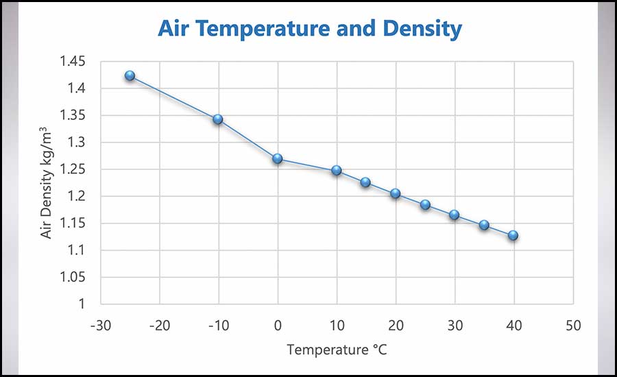
FIGURE 13: A variation of air density with temperature readings.
How to Remedy Performance Degradation
To start to close this article from where it began, there should now be an understanding of why gas turbines lose performance and the variants associated with their location and operation. A range of methods have been identified that can help the operator recover lost performance. The key to unlocking the problem is first to understand the issue. That means that every location should be treated as a unique application and due consideration should be given to the operating conditions and the requirement from the site in terms of generating power. The starting point is to understand the air quality and, more importantly, how it changes throughout the year in terms of particle concentration and temperature.
This, then, provides the information necessary to design the inlet filtration system and whether or not some type of power augmentation system is required. If it is believed the inlet filtration system will be compromised or require support in its operation, perhaps compressor washing could be included, either offline or online.
When making any changes to an operation, it is advisable to establish a baseline of production so that the benefits can be measured. Performance analysis tools are available, and there are companies that will offer this as a service. However, the best way to check performance is when the gas turbine is operating at base load with the inlet guide vanes (IGVs) fully open. It is often a case of recording the ISO-adjusted power output and fuel flow to give a snapshot of performance in terms of power output against fuel used. It is also an excellent idea to monitor the pressure drop across the inlet filters.
Conclusion
It has been made clear that there are many options available to the gas turbine operators in terms of maintaining the unit’s performance. Equally, there is not one solution that suits all applications. It is more important that the operator be able to recognize the challenges and then investigate how they can be overcome. It is relatively easy to approach one company and ask for the answer: A filter manufacturer will advise a certain filter, power augmentation companies will recommend their products, and, likely, the compressor wash company will be happy to supply a solution from within its supplies. In reality, appropriate performance recovery may be a combination of all three solutions to some degree, but, more importantly, it is the ability to measure and quantify gas turbine performance losses on a regular basis that is important.
References
1. Horlock, J. H., 1992. Combined Power Plants, including Combined Cycle Gas Turbine (CCGT) plants. Pergamon Press, Oxford (1992), Energy, V18, Issue 6, ISSN 0360-5442.
2. Zwebek, A., 2002, Combined Cycle Performance Deterioration Analysis (PhD Thesis), Cranfield.
3. Williams, L. J., 1981, The Optimisation of Time Between Overhauls for Gas Turbine Compressor Units (4th Symposium of Gas Turbine Operations and Maintenance edition), In N.R.C of Canada, Canada.
4. Zwebek A, Pilidis P., 2003. Degradation Effects on Combined Cycle Power Plant Performance Part III: Gas and Steam Turbine Component Degradation Effects. J Eng Gas Turbines Power 126(2):306e15.
5. Nikolaidis T & Pilidis P., 2014. The Effect of Water Ingestion on an Axial Flow Compressor Performance, Proceedings of the Institution of Mechanical Engineers, Part G: Journal of Aerospace Engineering, 228 (3) 411-423.
6. H. Cohen, G.F.C. Rogers, Paul Straznicky, H.I.H. Saravanamuttoo, Andrew Nix. Gas Turbine Theory, 2017. Seventh Edition. Pearson.
7. Al-Attar I.S., 2011. The Effect of Pleating Density and Dust Type on the Performance of Absolute Fibrous Filters, doctoral diss., Loughborough University Institutional Repository.
8. Tarleton E.S. and Wakeman R.J. 2008. Dictionary of Filtration and Separation Filtration Solutions, Exeter.
9. Brown R.C. 1993. “Air filtration: an Integrated Approach to the Theory and Application of Fibrous Filters”, Pergamum Press, Oxford.
10. Davies C.N., 1973. “Air Filtration”, Academic Press, New York.
11. DIN 1822-1, 1998. “High Efficiency Air Filters (HEPA and ULPA)” - Part 1: Classification, performance testing, marking.
12. Particulate Air Filters for General Ventilation - Determination of the Filtration Performance; German version EN 779:2012
13. Wakeman R.J., Hanspal N.S., Waghode A.N. and Nassehi V., 2005. Analysis of Pleat Crowding and Medium Compression in Pleated Cartridge Filters, Chem. Eng. Research and Design, 83(A10), 1246–1255.
14. Wakeman R.J. and Harris, P.R., 1993. A Methodology for Modelling Flow in Pleated (Star) Filter Cartridges, Proc FILTECH Europa, Karlsruhe, 335–343.
15. Al-Attar I.S., Wakeman, R.J., Tarleton, E.S., and Husain A., 2009. The Effect of Pleat Count and Air Velocity on the Initial Pressure Drop and Fractional Efficiency of HEPA filters, Filtration Journal, 10 (3), 200-206.
16. Abdullah A.A.A. Al-Rashed, Abdulwahab A. Alnaqi, Jalal Alsarraf. Energy-Saving of Building Envelope Using Passive PCM Technique: A Case Study of Kuwait City Climate Conditions”. Sustainable Energy Technologies and Assessments. Volume 46, 2021, 101254, ISSN 2213-1388.


