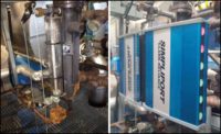
Water gage glasses continue to be a vital instrument on power boilers that are constructed to comply with the requirements of the American Society of Mechanical Engineers’ (ASME’s) Boiler and Pressure Vessel Code. The code requires that all boilers must be equipped with at least one water gage glass for good reason in addition to the other level-indicating instruments operators rely upon from remote control areas. The gage glass provides a ready determination of the water level for the operator, especially at critical times, including start-up, shutdown, and during testing of low water fuel cutout devices. A gage glass may also serve as a referee in the event two remote level indicators begin to disagree with each other. Causes for a dispute with the displayed level between multiple remote indication systems may include sludge buildup in sensing lines, restricted valves, or a component failure on one of the instruments.
There are four common types of water gage glasses currently used in the boiler industry. They are illustrated in Figure 1 with industry standard maximum pressure ratings.
Section I (for boilers above 15 psi) of the ASME Boiler and Pressure Vessel Code specifies the lowest visible elevation of the water gage glass. Prior to the 2019 edition, this elevation for watertube-type boilers was required to be located at least 2 inches (50 mm) above the danger point, as determined by the boiler manufacturer. The latest edition (2019) of the code requires the gage to cover the full operating range on all boilers, and the lowest visible elevation must be 2-3 inches (50-75 mm) above the danger point for water tube- type boilers. The requirements for fire tube - type boilers are based on the drum diameter (See Figure 2.)
This updated requirement prevents the use of a short-range gage glass with limited effectiveness as a feeble attempt to meet the code. Typically, a short-range gage may not enable the operator to confirm elevations where alarms or trips actually actuate.
In addition, the requirement for the extremes of the vision range on a water gage glass are not permitted to encounter the pipe diameters that exit the vessel. This requirement has been in the code for years. The reason for this requirement is to prevent a gage from being installed too low, which may trap water from draining back into the boiler drum or from being installed too high that it may not indicate the upper level accurately.
The guidelines for proper positioning of a gage glass are illustrated in Figure 2. Level “A” is the danger point, which is determined by the boiler manufacturer. If there is any doubt about the locations of alarm or trip levels relative to the drum centerline or nozzle connection centerlines, consult the documentation that was provided with your boiler for details.
Users and operators should consider the following tips and benefits to properly maintain their water gage glasses.
- Make sure the gage is kept clean and properly illuminated to enable the operator to view the level from the operating floor or platform. The gage glass assembly should be properly installed so the operator can view the level from the intended location. Lighting accessories are available from most manufacturers to aid with challenging installations.
- Isolation and drain valves must be installed. The outlet of the drain valve should be routed to a safe discharge location.
- Use a maintenance log for your water gage glasses and inspect them and the related valves routinely. If you remedy any concerns as they arise, the risk and cost will be minimized.
- Use OEM parts and instructions to service these critical instruments. As improvements evolve, the OEM has the most accurate information for the component parts and repair procedures to maximize service life and safety.
- Violations during annual inspections can be prevented with proper maintenance.
In fact, all power boilers must have a gage glass in operable condition. Boilers operating up to 400 psi are required to have one gage glass in service at all times. On applications operating above 400 psi, the gage glass may be isolated, only if there are two independent remote level indicators on continuous display for the operator in the control area. However, many plants operate with gage glasses in service on these applications to provide constant level indication availability for their operators as they walk down the boilers and to meet plant-specified procedures.
In summary, we suggest users consult with their own safety staff, insurance carrier, and local jurisdiction inspection authority to verify any specific requirements for their particular location. An additional resource for helpful information is ASME Section VII, “Recommendations for the Proper Care of Power Boilers.” This publication includes helpful information for operators and owners.


