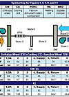
FIGURE 1. Enthalpy wheel (EW), cooling coil (CC), and sensible wheel (SW) arrangements.
EDITOR’S NOTE:ThisEngineered Systems Web Exclusiveversion of the article that appeared in the print issue features additional content including figures and tables.
This pairing can represent a great strategy - if you choose your tactics wisely. When is passive or active the better desiccant approach? When is one out of the question? We'll discuss how to control the latent load, arrive at a smart design decision for the circumstance, and consider recent research on first cost and performance.
Two essential attributes of mechanical systems intended to provide building occupants with good IAQ and indoor environmental quality (IEQ) are uncompromised ventilation air delivery and ensured humidity control.
Engineers have numerous mechanical system selection options at their fingertips as they labor to achieve the two attributes; however, most options fail one or both of the required attributes. One mechanical system, discussed here and capable of economically meeting the essential attributes, is a properly designed dedicated outdoor air system1. DOASs are designed to deliver at least the minimum 100% OA specified by ASHRAE 62.1 to each occupant, and to completely and continually meet the individual space latent cooling loads with dry air.
FIGURE 2. Psychrometric chart for CC and EW+CC.
Selecting the DOAS supply air dewpoint temperature (DPT)
A DOAS, delivering the required ASHRAE 62.1 ventilation air, rarely supplies more than a small fraction of the air delivered by an all air system, such as a VAV. Consequently, the DOAS is seldom able to meet the space sensible loads, even if the supply air (SA) drybulb temperature (DBT) is low (40°F to 50°), thus requiring parallel sensible cooling equipment. The design engineer must make a conscious decision to allow the parallel cooling equipment to also meet either none or a part of the space latent load.Some parallel cooling equipment can accommodate latent cooling (e.g., fancoil units). Other parallel cooling equipment - such as chilled ceilings, beams, and floors - must not be allowed to handle any of the space latent load, in order to avoid condensation on the cool surfaces.
Even when the terminal equipment is permitted to remove moisture, the drain pans become a septic amplifier throughout the facility and may adversely affect the IEQ and IAQ. Consequently, one should generally assign the DOAS the entire task of moisture removal, both in the OA and within the occupied spaces.
When the DOAS has the task of removing all moisture generated and/or leaked into the occupied spaces, the required supply air DPT is a function of the design space DPT (related to the design space DBT and % rh), the latent load, and the rate of DOAS SA to an individual space. Each individual space needs to be scrutinized.
The functional relationship is as follows:
QL=0.68 x scfm x(Wspace-Wsupply),
Where QL is the space latent load in Btuh, scfm is the space DOAS SA flow rate expressed at standard temperature and pressure, Wspace is the desired design humidity ratio in gr/lbm (7,000 gr/lbm), and WSupply is the required SA humidity ratio in gr/lbm.
If a space had a latent load from people, infiltration, plants, etc., of 1,280 Btuh; a design space condition of 75°; 45% rh (Wspace=58 gr/lbm), and a SA flow rate of 125 scfm; solving the equation above for Wsupply, yields 43 gr/lbm. That corresponds to a DOAS SA DPT requirement of 45°.
Clearly, 45° DPT is below the ordinary 52° DPT associated with conventional VAV. Increasing the SA flow rates to the space requiring the lowest SA DPT (generally at the perimeter) will allow the design DPT to be increased, relaxing the SA DPT required for the entire facility.

FIGURE 3. Psychrometric chart for EW+CC+SW.
Other techniques
The lower than normal SA DPTs have led some to employ low temperature techniques, others to use ice thermal storage and associated low chilled water/brine temperatures, and still others to employ desiccants (active desiccant and passive dehumidification components) with conventional temperature DX cooling equipment.Desiccants use either adsorption or absorption to attract water molecules to accumulate at the desiccant. Adsorption is the process that occurs when a gas accumulates on the surface forming a molecular or atomic film (adsorbate). Absorption is the process where gas molecules, atoms, or ions diffuse into the solid desiccant to form a solution. Adsorption desiccants include zeolites (molecular sieve) and silica gel. Absorption desiccants include hygroscopic salts such as lithium chloride.
Some practicing engineers have found that SA DPTs no lower than 50° will still remove all of the space latent loads in practice. When this is the case, the ventilation airflow rates were selected for occupancy higher than actually realized, which is common. And/or the occupancy is transient, and the DOAS SA flow rate is constant (i.e., no demand controlled ventilation) and the building contents and enclosure are absorbing moisture, thus limiting the space % rh even when fully occupied.
DOAS equipment in the marketplace
Due to limited space, this article will not discuss all equipment. However, let's attempt to cover the general classes.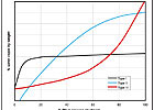
FIGURE 4. Representative sorption isotherms for three desiccant types at 75°F.
No energy recovery class
The simplest and lowest first-cost class is simply a cooling coil (CC) used to suppress the SA DPT to 52° (removing all the OA latent load, but only part of the space latent load), and allowing the parallel equipment to take care of the balance of the sensible and latent loads not accommodated by the ventilation air. For all buildings except low-rise residential, ASHRAE 90.1 would limit this class to buildings where the DOAS is handling less than 5,000 cfm. The 52° SA DOAS mimics a VAV system when the VAV box has modulated to the minimum air mode. Neutral air temperatures would never seem to be desired. Modulating the ventilation airflow rates based upon occupancy could save cooling or heating energy at off-design occupancy ventilation rates, since there is no heat recovery in this class.Rarely, if ever, would the 52° SA DPT accommodate all of the space latent loads, so it could not be used with chilled ceilings, beams, or floors.
Caution required
Great care needs to be exercised when selecting such a DOAS, since the unit handles 100% OA and will experience very high latent to total loads (small sensible heat ratio [SHR]). That is something most off-the-shelf DX units are not capable of. Since the SHR for most packaged DX equipment is about 0.7, the high latent loads of the OA require equipment capable of delivering sensible cooling well beyond the needs. To prevent overcooling, the equipment cycles on and off without providing adequate dehumidification, unless equipped with reheat.This class is not generally a good candidate for DX equipment. An exception is pool dehumidification equipment designed to maintain space % rh with low coil temperatures, and hot refrigerant gas reheat, as necessary, to prevent excessive space sensible cooling.
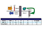
FIGURE 5. Passive dehumidification component (PDHC) and CC without energy recovery.
Total energy recovery class
The next step in the progression of DOAS equipment classes adds a total energy recovery (TER) component (wheel or plate type) upstream of the CC to recover total energy from the exhaust airstream. TER (employing passive desiccants) is not able to drop the SA DPT low enough to do space dehumidification by itself, so a CC is still required. ASHRAE 90.1 requires TER (for most climates) in all but low-rise buildings when the DOAS is handling 5,000 cfm or more. The TER device employs a desiccant that is regenerated without the expenditure of auxiliary heat. Wheel-type TER components, also referred to as enthalpy wheels, typically rotate at about 20 rpm or higher.A TER component does not perform psychrometrically like an active solid desiccant wheel (which requires regeneration temperatures of 150° to 300° and operates at about 1/6 to 1/2 rpm). Active desiccant behavior approximates a constant enthalpy process (temperature increases as the humidity ratio decreases, and vice versa). The active desiccant wheel's low rotational speed limits the sensible heat transferred between the process and regeneration airstreams. The TER device performs psychrometrically like the adiabatic mixing of two airstreams (that is the leaving conditioned air state point is on a straight line between the two entering air state points).
TER equipment often exhibits effectiveness between 0.6 and 0.8. That means the TER device will condition OA, for example, along a straight line between the OA and relief air conditions, to within 20% to 40% of the relief air state point. The result is a huge reduction in the CC load, a great reduction in the variability seen by the CC, and most importantly, a great reduction in the latent component of the coil load. This makes it possible for ordinary off-the-shelf DX cooling equipment to handle the 100% OA loads. Design SHR for coils handling 100% OA are about 0.3 to 0.4, while the SHR capability of most packaged equipment is about 0.65 to 0.82.
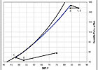
FIGURE 6. PDHC+CC psychrometric chart.
Illustrating the SHR issue
To illustrate the SHR issue, assume a 20-ton CC (working alone) cooling and dehumidifying 100% OA. Also assume that the CC is required to meet a SHR of 0.35 (35% of the total load is sensible cooling and 65% is latent cooling). That means the sensible load is 7 tons and the latent load is 13 tons.If a conventional 20-ton DX unit were selected for the application capable of handling a load with a SHR of 0.7, it could do 14 tons of sensible cooling and 6 tons of latent cooling - less than half the required latent cooling.

FIGURE 7. One arrangement of PDHC and CC with EW (EW+CC+PDHC).
Low DPTs are not friends of DX equipment, and chilled water (brine) systems require lower than normal fluid temperatures. So unless ice storage is used as the cooling source, the TER-CC class is generally limited to SA DPTs around 50° to 55°. With this class of DOAS, assuming a good TER effectiveness (>0.7), there is very little cooling or heating energy savings by modulating the SA flow rates at off design occupancy, thus eliminating the need for demand controlled ventilation (DCV) employing VFDs and extensive CO2 monitoring and controls. The small additional operating cost resulting from the extra energy utilized with a constant volume DOAS is more than offset by the first cost of DCV.

FIGURE 8. EW+CC+PDHC psychrometric chart.
Maintaining building pressure
When applying TER, care should be exercised to assure that building pressurization is not lost in an effort to maximize energy recovery.Finally, use of wheel type TER devices is not recommended if the exhaust airstream contains dangerous material (private toilet and several other exhausts are approved for the TER devices as documented in ASHRAE 62.1, sections 5.17.1 Classification and 5.17.2.2 Energy Recovery). When this class is used to mechanically produce low DPTs, (in the low 40°s) when a higher SA DBT is needed at design or off-design, then consider either hot gas reheat or sensible heat recovery from the exhaust airstream for energy efficiency.
A schematic of a system in this class consisting of an EW, CC, and SW is illustrated in Figure 1, along with the tabular thermodynamic state points throughout the system for the CC alone, EW+CC, and EW+CC+SW. The psychrometric process for the CC and the EW+CC are presented in Figure 2. Observe the dramatic reduction in the CC load, approximately 40%, when the EW is added. Adding a SW to the EW+CC arrangement allows the supply air temperature to be higher than the coil leaving temperature when the sensible loads are low.
Figure 3 illustrates the psychrometric process for the combined EW+CC+SW. Perhaps not obvious at first inspection, the reduction in the CC load is not as great as the lost SA sensible cooling due to a less-than-unity EW effectiveness. As a result, any time the SW is operating and a parallel system is providing sensible cooling in the space, the total cooling load on the plant is higher than if the SW were not operating.
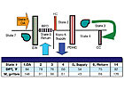
FIGURE 9. A second arrangement of PDHC and CC with EW (EW+PDHC+CC).
Passive dehumidification component class
When low SA DPTs (less than about 48°) are required, they can be achieved with normal DX or chilled water CC operating temperatures with the aid of a passive dehumidification component (PDHC). The PDHC consists of a type III desiccant wheel, whose performance is characterized in Figure 4. Notice that the PDHC exhibits maximum moisture holding (removal) capability when the entering air % rh approaches 100%, typical of the condition leaving a CC. Conversely, when the entering air % rh drops below 80%, the ability of the PDHC to hold moisture drops rapidly.The rate of moisture removal is a function of the two entering airstreams' thermodynamic state points. If the % rh of the reactivation air is too high for the desired rate of transfer, a heating coil can be used to reduce the % rh, thus increasing moisture transfer rates.
One arrangement of these components serving the DOAS market is illustrated in Figure 5. In essence, the PDHC wraps around the CC. One hundred percent OA enters the PDHC where moisture is added to the airstream in an endothermic reaction nearly adiabatically, causing the air/water vapor mixture temperature to drop anywhere from 3° to 9°. The air/water vapor mixture is further cooled and dehumidified with the CC operating at conventional temperatures (leaving air temperatures of 50° to 55°). Finally, the 100% OA enters the other side of the PDHC where moisture is removed in an exothermic reaction, thus elevating the leaving air temperature 3° to 9°. The moisture removal is sufficient to lower the leaving air DPT by up to 10° below the CC leaving air DPT.
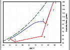
FIGURE 10. Psychrometric chart depicting EW+PDHC+CC.
In the PDHC+CC case, 5,000 cfm of air is cooled to 50.6F DBT and 49.3F DPT at the CC using 45° chilled water, then dehumidified further with the PDHC to 54.7° DBT and 42.3° DPT. The CC was operating at 18.5 tons, and the system was using 20.9 kW (1.1 kW/ton). In the standalone CC case, 5,000 cfm of air at 42.8° and 42.1 DPT was produced with 38° brine. In that case, the standalone CC load was 25 tons and the system was using 30.9 kW (1.2 kW/ton). The standalone CC system was using about 9% more power per ton of cooling, and the coil load was 6.5 tons greater, but it was doing 5.4 tons more space sensible cooling. To the manufacturer's credit, a reheat penalty was not added to the analysis involving the standalone CC, unlike most desiccant manufacturers' marketing documents. That is good, because rarely is reheat needed when cold ventilation air is introduced into spaces, making arguments for neutral SA DBTs invalid.
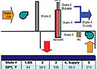
FIGURE 11. Active desiccant wheel and CC arrangement.
Taxing the system
If a system were to produce cooling for 2,000 hrs/yr, with an average CC load at 50% of design, the difference in operating cost per year would be $370, based on $0.10/kWh. There is a significant first cost burden when adding the PDHC, with a negligible reduction in the cooling plant size when equivalent loads are considered.The manufacturer's psychrometric performance of the PDHC+CC equipment for a demanding cooling day, OA is 84° DBT, 148 gr/lbm is presented in Figure 6. Notice that the design condition taxed the system. Conditions were simulated with the manufacturer's software for preheat from zero to 19°. Only the 5.5° preheat is presented in this article. Increasing the preheat, resulted in increased cooling coil loads, elevated SA temperatures, and ever increasing preheat energy input.

FIGURE 12. Psychrometric chart depicting active dehumidification.
Integrated EW, PDHC, and CC dehumidification class
Continuing the development of classes of equipment aimed at DOAS dehumidification, consider adding TER to the PDHC+CC equipment class. Two currently available pieces of packaged DOAS equipment that integrate EW, PDHC, and CC are illustrated in Figures 7 (EW+CC+PDHC) and 9 (EW+PDHC+CC), along with thermodynamic state point conditions (for a demanding cooling day, OA is 84° DBT, 148 gr/lbm) as determined by respective manufacturers' selection software.The main difference between the two packages is the order and use of the PDHC. The state points for these packages are also presented psychrometrically in Figures 8 and 10 respectively. In these examples, both packages produced 43° SA DPTs but different SA DBTs of 63.3° and 54°, respectively. Significantly, the DBT leaving the CCs (53.4° and 50°, respectively) is achievable with conventional DX and chilled water CC temperatures. The CC load for the EW+CC+PDHC system is 20 tons, and 25.5 tons, for the EW+PDHC+CC system.
However, the EW+CC+PDHC system SA delivers 4.6 tons less sensible cooling than the EW+PDHC+CC system. When the extra sensible cooling needed at the terminals for the EW+CC+PDHC system is added, the performance of the two systems is nearly equivalent - differing by about 1 ton; with the EW+PDHC+CC system requiring about 5% more load in this example.
The psychrometric processes for the PDHC (points 3 to 4 and 5 to 6 in Figure 8 and 2 to 3 and 4 to 5 in Figure 10) reflect the nearly constant enthalpy trends typical of a desiccant (rotating very slowly - less than one rpm), as opposed to that of a TER device, rotating at about 20 rpm. Placing the CC before the PDHC as in Figure 7, allows the CC to operate at a warmer temperature and less load while maximizing the moisture transfer with the PDHC. Wrapping the PDHC around the CC, as in Figure 9, requires a lower CC discharge air DBT and increases the load thereon. The moisture removal capabilities of the PDHC are less in this arrangement than with the Figure 7 arrangement. But since the SA DBT leaving the PDHC is lower than the Figure 7 arrangement, it is able to do more sensible cooling.

TABLE 1. Energy demand for various DOAS arrangements conditioning 100% OA from 84
Integrated active desiccant wheel/cooling coil dehumidification class
This class of dehumidification is especially well suited for applications where return air is not available for energy recovery, and where SA DPTs below about 50° are desirable. One commercially available arrangement is illustrated in Figure 11. Outdoor air is initially cooled and partially dehumidified with a CC. A portion of that air is then deep dehumidified with the active desiccant wheel (ADesW), which is reactivated with air at over 200°. The dehumidified air leaving the ADesW at 108° and 24 gr/lbm is mixed with the air at the CC leaving temperature, which by passed the ADesW, in a ratio that is delivered to the space at 88.5° and 43 gr/lbm.The psychrometric performance of the OA as it passes through this unit is illustrated in Figure 12. This particular packaged unit is not adequate for the example illustrated in the article. The manufacturer offered that a custom unit could be built to better suit the conditions of the example. Beside the large CC load and the extra terminal cooling added with the hot SA DBT, it uses 234,000 Btuh of regeneration heat energy. While this is quite different than advertised, it is not unlike the findings of an ASHRAE-sponsored research report to be presented later in this article.
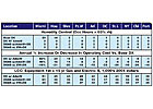
TABLE 2. 6,000-sq-ft, single-story office facility humidity control and annual operating cost compared to a base DX cooling system.
Energy demand comparison by class at peak OA latent condition
On the basis of the equipment and conditions presented above, the following energy demand was computed and presented in Table 1, when 5,000 cfm of 100% OA at 84° and 148 gr/lbm was dehumidified to 43 gr/lbm.There are many considerations when ranking the different arrangements. One of the important considerations is the potential for overcooling when the SA DBT is low, thus requiring terminal reheat and possibly energy waste. Another consideration is the CC operating temperature. The cooling plant is derated at low temperatures, increasing first cost, and the kW/ton increases with decreasing CC operating temperatures. Finally, as wheels are added to the air paths, the fan power is increased, sometimes significantly. The ranking system used is based upon simplicity, the probability of wasteful terminal reheat at the given SA DBTs, and subjective first and operating costs.
The author's top choice for cases where low SA will not cause terminal reheat to be necessary is arrangement 2, EW+CC, with arrangement 5 very close behind. The top choice for cases where low SAs will cause considerable terminal reheat is arrangement 5, EW+CC+PDHC.
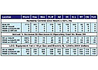
TABLE 3. 79,000-sq-ft, single-story retail facility humidity control and annual operating cost compared to a base DX cooling system.
ASHRAE research results related to some classes in 10 geographic locations
The ASHRAE research project final report, 1254-RP, "Evaluating The Ability Of Unitary Equipment To Maintain Adequate Space Humidity Levels, Phase II," is the result of cooperative research between the ASHRAE, and GARD Analytics, Inc.3. Space does not permit all of the results to be presented (the final report is available online at the link in the references). The ASHRAE research did not analyze systems utilizing PDHCs. The modeled airflow rate per ton of cooling ranged from 300 to 400 cfm/ton of cooling, corresponding to saturated SA temperatures of 48° and 52°, respectively.The terminology used in Tables 2 through 4, DOAS w/ADesW + DX and DOAS w/ EW+DX recognizes that the DOAS is not capable of providing all of the space cooling due to the low ventilation airflow rates, and requires a parallel cooling system - DX in the research project. The base DX and the DX w/ADesW were each sized to satisfy the entire space loads.
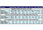
TABLE 4. 350-sq-ft, hotel room humidity control and annual operating cost compared to a base DX cooling system.
Superior for office and retail
Clearly, humidity control, annual operating costs, and LCC for DOAS w/ EW+DX are superior for office and retail applications. The results did not favor DOAS w/EW+DX for the 350-sq-ft hotel room with respect to room humidity control; otherwise, it did well. The poor humidity control is a reflection of improper system sizing for the analysis, rather than an innate inability of the DOAS to control humidity. Where high latent generation is present relative to occupancy, either the rate of ventilation air must be increased or the SA DPT dropped.Conclusions and recommendations
Providing the correct ventilation and space % rh for the purpose of achieving good IAQ can be ensured with DOAS systems. There are many DOAS components and arrangements, with some better able to meet the space % rh than others. Since the SA DPT and flow rate are the critical factors used to limit the maximum space % rh, they are the chief performance parameters of importance. The SA DPT in some instances must be below 50°. As the SA DPT requirement decreases, desiccant components become attractive tools that permit the CC temperatures to remain near normal (around 45°).The reliable availability of desiccant based EWs is also an extremely useful tool for the engineers toolkit, since integrating it with the CC allows major reductions in both the OA latent load and the chiller design capacity. For most commercial and institutional applications, the arrangements that employ EW+CC or EW+CC+PDHC seem to offer the best balance between IAQ and LCC.
