
How many incorrect assumptions about lab and health care ventilation requirements have you seen incorporated? Have you ever thought of the real cost for speed of response and type of control mechanism for a specific application? Visit these case studies to see what needs to be considered for real every day applications before making an informed choice.
For years, constant air volume (CAV) systems have been the traditional choice when choosing ventilation systems for laboratories and health care facilities. Recently, VAV systems have increased in popularity as an alternative that improves energy efficiency. VAV vs. CAV, is one better than the other? Is that the right question to ask?
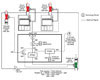
Figure 1
Readers will learn how to choose the appropriate solution based on process needs, client requirements, environmental health and safety issues, and sustainability goals.
Learning Objectives
The learning objectives of this article are to understand the differences between the two approaches - in effect, what makes a system CAV or VAV and why choose a fast actuator, does it bring any benefit. There are two main differences that define the systems.The first consideration is at the AHU. Specifically, should the AHU be fitted with a motor starter (MS) or a VFD?
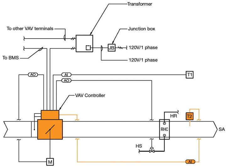
Figure 2
For a small premium, a VFD can be fitted to the AHU, which would allow the right sizing of the AHU as the VFD will make an allowance for the filter loading. The VFD will also allow for spare capacity this can be built into the unit without requiring major changes later. The payback for adding a VFD for filter loading alone is attractive and more than compensates for initial add in first cost.
The second consideration is at zone level. Should the system be fitted with a CAV device or a VAV device? The device can be a simple box with a damper or Venturi valve.
Figure 3
VAV devices traditionally provide a variable flow rate to the space, this is not always the case there may be other reasons why a VAV device may be more suitable. The VAV device comes with controls that can measure a setpoint within the space being controlled, as well as normally temperature, humidity, CO2, and/or some other parameter and modify the device mechanism position depending on the desired output.
For most cost effective solutions neither CAV nor VAV devices, give feedback to the BMS with regards to how much flow is actually going through the device; this type of control is known as an open-loop control. As an alternative, an airflow measuring station can be added to each device to measure the actual flow through the device regardless of all the other parameters it is trying to monitor and or control. This will provide feedback to the BMS to self-check the parameters it is trying to control and automatically adjust the mechanism to provide the actual flow required to achieve the setpoint. The closed-loop control is recommended when the relationship between the supply and/or return/exhaust is critical to maintain a preset differential between the supply and or return/exhaust flow rates. For critical spaces, where a high degree of accuracy is required and the allowable temperature variation is small, more intelligent controls are available where algorithms are written to fine tune the air flow rate taking into consideration the set point, the current condition of the space and actual supply air rate and condition. This type of system control can estimates in advance the outcome before adjustment.

Figure 4
More complex electronic systems can provide feedback to the BMS. This feedback can then be used to control the differential between the supply and return/exhaust and/or provide information to the users that the pressure differential is not being maintained. To avoid false alarms due to opened doors, sensors can provide further control feedback to allow the opening of doors to an adjustable preset time before an alarm signal is initiated.
The cost difference between CAV and VAV devices is approximately 25% increase to pay for the VAV system. These systems normally have very good life-cycle payback when energy cost is factored into the life-cycle cost analysis. In reality, when budgets are constrained, the VAV device, unless absolutely critical for operation purposes, is often value-engineered out.
The speed of actuation and the type of device used (e.g., damper or Venturi valve-type) on the supply and return/exhaust is the more important cost factor. Actuator speed can double the cost of the device. Designers need to consider how critical is the process and future flexibility of the facility when deciding the speed of actuator.
Where there are space constraints for installation, the Venturi valve is more forgiving, because in general, the damper-style can require up to three duct diameters before and after the device. In health care and lab projects, which are generally heavily serviced, the luxury of space is not always available.
At the zone level, engineers have to consider a number of parameters before choosing the appropriate system for their circumstances.
- What is the quantity of air required for heating, cooling, and processes?
- What is the minimum outside air requirement?
- Peak requirements vs. short term conditions?
- Are air change rates the driving factor?
- What are the operational requirements during occupied mode?
- What are the operational requirements during unoccupied mode?
- What are the operational requirements during emergency mode?
- How critical is the process?
- What are the space constraints for constructability?
Opportunities and Applications
In general, laboratories and health care projects are leading the way in reducing energy consumption. For years, many designers have been under the following impressions.- Labs and health-care projects have to have constant airflow.
- These project types must have a minimum air-change requirement at all times.
- Code does not allow us reduced air-change rates.
- Fume hoods and biosafety cabinets (BSC) have to run all the time.
- Calculations must be made for peak requirement and design for the worst-case scenario.
- All fume hoods and BSCs run at the same time.
- The device being put forward by lab planners and or users must be accepted without challenging the device size and or type for the application and or process.
Figure 5
With the exception of hazardous chemical storage, there is no code requirement for minimum air change rates in labs. There is no code requirement that states systems have to run 24/7, especially fume hoods and BSCs. If these devices are emptied when not in use, they can be turned off. A number of documents provide guidelines that have been used by designers; however, these are not mandatory.
Owners and designer need to look for opportunities for innovation instead of excuses why something should not be done. Asking the right questions and challenging past practice will open up new opportunities and the thought process necessary to select:
- The correct size of equipment for the experiments;
- The type of equipment to carry out the experiments;
- The correct type of system servicing the space for the process in the room.
So far we have looked at the difference between CAV and VAV systems and parameters we need to consider to choose the correct system. The following case studies illustrate the effect of this decision making process on some real-life projects.
Case Studies: Columbia College Sonora Science Building
This project is a multidiscipline teaching science lab for a community college in the foothills of the Sierra Nevada. The challenges of this project are:- The prairie setting for the campus;
- No natural gas;
- Program changes;
- Wide variety of experiments;
- Budget.
A number of general classroom and lecture rooms were included in the program, for which the user wanted the flexibility to convert to labs in the future. The AHU and distribution was sized to account for the possible increase in ventilation; however, the actuators on the VAV system are slow acting and can be changed out if and when required.
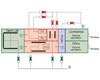
Figure 6
Case Study: UCSC Biomedical Science Building
This project is a multidisciplinary research lab for the University of California Santa Cruz. The challenges of this project were as follows.- Five-story building with a 20,000-sq-ft vivarium on the basement floor and a 20,000-sq-ft stem-cell research facility on the fourth floor.
- High number of fume hoods on each floor available to researchers 24/7.
- High quantity of heat-generating equipment requiring cooling 24/7.
- Backup ventilation for the vivarium and stem-cell research facility.
- Different flow rates for parts of the facility when unoccupied, with automatic override to establish the occupied ventilation.
The offices and conference rooms are located along the perimeter of the building, allowing us to use natural ventilation with radiant heating only.
The vivarium floor has a VAV system that varies the flow rate to maintain comfort conditions with a minimum setpoint to maintain minimum air changes within the space. The minimum and maximum setpoints are governed by whether the room has open or ventilated cages. The rooms with open cages have higher heat gains into the space and odors are more prevalent. To control this, ventilation is increased when required.
The vivarium floor also contains a sterilizer facility for cart washing with high heat-generating equipment. On this floor, the VAV system is an obvious choice to minimize the energy consumption, i.e., reduces the ventilation rate when the load is not present. Fast-acting actuators are not required, as there are no critical functions that would be jeopardized by a slow response. The exhaust valves serving this floor have a special coating due to the moisture-laden air from the sterile washing area and the ammonia within the exhaust from the holding rooms.
The four lab floors have similar layouts to achieve an energy-efficient solution. Fume hoods have been located in a number of central locations, which make use of transfer air from the main open floor lab area. Major heat-generating equipment is also located in a number of central locations that use transfer air from the main open floor lab area. The building façade has been designed to minimize the air required in the open lab areas to match the minimum air changes required in the lab area and meet the requirements of the transfer air required in the fume hood and equipment alcoves.
For further energy efficiency, a chilled-beam system was designed to meet the loads and minimum air changes within the space. Chilled beams can minimize the reheat component of a typical ventilation system considerably and provide a degree of self regulation. Calculations showed that we could use a CAV system to meet the load and minimum air changes.
Load calculations also showed that additional air would be required to achieve comfort conditions within the equipment alcove. Fancoil units (FCU) were added to each equipment alcove which operate automatically as and when required. By adding the FCUs, we were able to reduce the building ventilation rate in unoccupied periods and still maintain suitable conditions within the equipment alcoves.
With the exception of a few rooms in the stem cell facility, a two-position CAV system was used to satisfy occupied and unoccupied conditions. Actuators for the fume hoods are fast-acting response type.
Some rooms within the stem-cell research facility, have higher heat gains and critical pressure requirements, for these areas VAV valves with fast acting actuators and room pressure sensors have been specified.
The complete building is serviced via two AHUs, one for the vivarium and one for the remaining four floors. Only the branch serving the stem cell facility cleanrooms are fitted with HEPA filters. An additional booster fan has been provided to overcome the extra static pressure for the HEPA filters. The supply ductworks from the two AHUs are linked to provide backup to the vivarium and stem-cell facility. In the event of failure to the AHU serving the vivarium, the labs are shut down and their air is diverted to the vivarium and cleanrooms. The supply air branch serving the critical spaces in the stem cell facility is upstream of the ductwork link connecting the two AHUs to maintain uninterrupted flow to the stem cell facility. Without the VAV system on the AHUs and control devices on these two floors, this would not be possible without installing additional redundancy.
Case Study: Northbay Healthcare Vacaville Hospital
This project is an “I” occupancy hospital for Northbay Healthcare in Vacaville, CA. The objective of this project is to minimize the energy consumption of the hospital within the limitations of the California Energy Code – Title 24 and Office of Statewide Health Planning and Development (OSHPD) requirements.A number of AHUs have been provided to serve each individual department to allow for isolation during decontamination. The AHUs have been fitted with VFDs to compensate for the high filter loads that are prevalent with requirement of HEPA filters. All rooms will be fitted with VAV boxes on the supply and exhaust system to provide individual room control. No fast-response actuators are required in this facility; however gas-tight shut off is required to allow for decontamination of each department. The code allows a reduction of ventilation for a number of conditions, including the following.
- The number of air changes can be reduced to 25% of the minimum air changes required when the room is unoccupied, as long as the correct ventilation is reinstated when the room is reoccupied.
- Pressure relationship shall be maintained when air changes are reduced.
- Ventilation can be turned off in rooms that do not require a minimum air change rate and pressure regime.
- Ventilation cannot be reduced in rooms requiring infection control.
- Operating and delivery rooms shall have in minimum of six air changes at all times.
- The code allows for either a 100% outside air system or a system with recirculation. For each case, depending on the program, an analysis should be carried out to see which system is more cost effective and energy efficient.
The above allowable features are as implied in the current California Mechanical Code and meet the requirements of OSHPD; this will change for different states.
