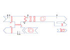
FIGURE 1. Constant volume (TRH) system.
In this forthright first installment, the author makes the argument that VAV as practiced for the last 50 years has become not only outdated but unable to keep up with the standards that are supposed to guide it. On the upside, circumstances point the way toward a revitalized, high-efficiency era for VAV. But first, let’s take stock of the status quo.
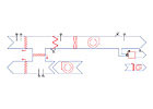
FIGURE 2. Shutoff VAV system.
The term “variable air volume” does not describe a unique system, but rather an air delivery strategy in which the rate at which air is delivered to a space is proportionally reduced with declining cooling loads. These systems reduce energy use at the direct expense of ventilation. Ventilation reduction is the primary cause of IAQ problems.
Because of these characteristics, simultaneously complying with the requirements of both ANSI/ASHRAE Standard 62.1-2004, “Ventilation for Acceptable Indoor Air Quality,” and ANSI/ASHRAE/IESNA Standard 90.1, “Energy Standard for Buildings Except Low-Rise Residential Buildings,” with classical VAV systems is a very difficult design challenge. The intent of this article is to explain why VAV systems are problematic to design. It is necessary to understand a challenge before it is possible to solve it. Only with that knowledge is it possible to address these shortcomings and take VAV system performance to its real potential. Part II will discuss some specific approaches to addressing these challenges.
IAQ
Energy conservation measures in the late 1970s focused on increasing building insulation levels, reducing the impact of infiltration, improving equipment efficiencies, and reducing outdoor air ventilation rates.The implications of tighter building construction and reductions in minimum ventilation rates for the ability of HVAC systems to provide an acceptable climate within buildings were simply not appreciated by the design community at that time, and problems first began to be noticed in the early 1980s. By the late 1980s, IAQ had become a matter of serious concern. Studies concluded that more than 95% of the air quality problems were due to inadequate levels of ventilation. In retrospect, the development of IAQ problems in buildings was a direct, logical, and predictable consequence of measures taken to reduce building leakage and ventilation rates.

GRAPH 1. Total airflow delivered.
The Importance Of Applicable Standards
Meeting the requirements of ANSI/ASHRAE Standard 62.1-2004 and ANSI/ ASHRAE/IESNA Standard 90.1-2004 are not merely prerequisites for LEED® certification. The ventilation requirements of all model building codes in the United States are derived from various editions of ASHRAE Standard 62, typically incorporating the ventilation rate tables and requiring the use of the multiple spaces equation. The 2007 International Mechanical Code (IMC) has already adopted the revised ventilation tables and computational procedures first published in Addendum N to ANSI/ASHRAE Standard 62.1-2001, the first major changes to those procedures since 1989.Under Section 304 of the 1992 Energy Policy Act (1992 EPACT), all states were required to meet or exceed the energy conservation requirements of ANSI/ASHRAE/IESNA Standard 90.1-1989. The 1992 EPACT provided for the automatic review and adoption of revisions and/or successor standards to ANSI/ASHRAE/IESNA Standard 90.1-1989 by the DOE within one year of publication.
States are required to adopt and update their energy conservation code requirements within two years of adoption by the DOE. As a result, compliance with the requirements of ANSI/ASHRAE/IESNA Standard 90.1 is a matter of both building codes and federal statute in most jurisdictions throughout the nation. ANSI/ASHRAE/IESNA Standard 90.1 was updated in 1999, 2001, and 2004.
Both standards were prepared, and are maintained, on a continuous basis by ASHRAE in accordance with the requirements of the ANSI for “consensus” standards. As such, they are often interpreted by the civil court system as “minimum standard of due professional care” (Call vs. Prudential, 1992). For the above reasons, architects and engineers ignore these standards at their professional peril.
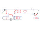
FIGURE 3. VAV reheat (VRH) system.
Standard 90.1 Compliance
The purpose of Standard 90.1 is to reduce energy use. It recognizes the need for ventilation as defined in ANSI/ASHRAE Standard 62.1, but places constraints on how designers are permitted to expend energy to deliver that ventilation. As the standards evolved, the recognition of the need for ventilation in that message did not change, but the restrictions on how designers are permitted to go about providing it have increased with each subsequent version. Standard 90.1 promotes the use of variable volume for its energy use reduction, but severely restricts reheat. In addition to requiring minimum equipment efficiencies, Standard 90.1 also limits fan system nameplate horsepower and mandates the use of energy recovery in specific situations.The use of reheat is prohibited under Section 6.5.2.1 of Standard 90.1-2004, and allowed only under limited exceptions. While permitting VAV reheat systems, the amount of airflow permitted to be reheated is no more than the greater of 30% of device design flow, 0.4 cfm/sq ft of area served, or the amount of outdoor air required to satisfy the space ventilation needs as computed in accordance with Standard 62.1. These restrictions have significant implications for the design of VAV systems.
For systems less than 20,000 cfm capacity, total fan motor hp is restricted to not more than 1.7 rated motor hp/1,000 cfm. For systems larger than 20,000 cfm, that number drops to 1.5 rated motor hp/1,000 cfm. This includes all fans, not just supply and/or return fans, but includes exhaust fans and those associated with fan-powered VAV boxes. Credits to this limitation are provided for increased air filtration and for the use of air-to-air heat exchangers and relief fans. This requirement forces designers to prepare detailed duct pressure drop computations and can force designers to increase the size of ducts and/or equipment specified to bring overall system horsepower within limitations.
GRAPH 2. Economizer controlled outdoor airflow delivered.
Standard 62-1989 Compliance
When published in 1989, Standard 62-1989 fundamentally and dramatically changed the rules of HVAC system design. The need for ventilation became a function of occupancy, minimum rates were substantially increased, and the designed systems had to deliver at least the requisite ventilation rate to each individual space under all conditions of load whenever the space was occupied. Those basic requirements have not changed with subsequent versions.Standard 62-1989 introduced a new method for computing the minimum outdoor air fraction necessary to accomplish acceptable levels of ventilation known as the “multiple spaces equation.” Much has been made of the complexity of the multiple spaces equation by a few determined opponents. However, when applied to constant volume systems (Figure 1), this equation itself is quite simple and readily computed and documented with a spreadsheet. It is intended for use with all constant volume systems serving more than one occupied space such as illustrated in Figure 1.
Standard 62-1989 required that the outdoor air fraction (Zi) be computed for each space, and the largest value be used to compute the requisite outdoor air fraction at the system level.
Y = X / ( 1 + X - Zc) (Equation 6.1)
where:
Y = the minimum outdoor air fraction of the system
X = the uncorrected outdoor air fraction
Zc = the outside air fraction of the critical space
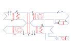
FIGURE 4. 100% outdoor air VAV reheat system.
The VAV Design Challenge
With constant volume systems, the value of Zi for each space will be unique from space to space, but it is essentially a constant. This is not true for VAV systems. While the requirements of Standard 62-1989 were clearly stated, Standard 62 was not explicit as to how the multiple spaces equation was to be applied to VAV system design until clarified in 2003 with addendum N to Standard 62.1-2001. While the methodology in addendum N also modified the prescribed methodology for the computations, a close inspection of the equations will reveal that the general form of the equation has essentially remained the same. So, for the purposes of keeping things simple, the pre-addenda N equation is used in this article.Classic VAV systems are typically controlled to respond to changes in space cooling loads by increasing or decreasing the amount of ventilation air provided. Compared to a constant volume system, a shutoff VAV system (Figure 2) is extremely efficient and provides excellent control over temperature and substantial fan energy savings. It is designed only to cool and does not require heating coils. But, it is a terrible system from the standpoint of ventilation. When ventilation is intended to be introduced through a mixed air path, a shutoff VAV system will terminate all ventilation to a space once heating is required. For this reason by itself, the shutoff VAV system cannot comply with the requirements of Standard 62.
The VAV reheat system is a variant of the single-duct VAV concept which is commonly employed when minimum rates of ventilation are determined to be necessary or desirable. It provides somewhat better ventilation characteristics than the shutoff VAV system as it does provide some level of ventilation. However, Standard 90 restricts the use of reheat, so the minimum rates of air delivery are restricted. In addition to reheat coils, the VAV reheat system typically requires some form of preheat and a methodology to make sure that adequate amounts of ventilation are introduced through a mixing process. This is much easier said than done and usually not done.

GRAPH 3. Outdoor air required.
System Ventilation Characteristics
A nominal 10,000 cfm example has been prepared to illustrate how these three alternatives differ in their ability to actually deliver the requisite amount of ventilation. The exact same load characteristics are assumed for all examples in Graphs 1 and 2 where the uncorrected outdoor air fraction (X) assumed for all three cases is 20%. The outdoor air fraction for the critical space is assumed to be 30% of full cooling load flow for the VAV reheat (VRH) and constant volume (TRH) cases.Graph 3 is used to illustrate the sensitivity of VRH strategies to the critical outdoor air fraction. The outdoor air fraction for the critical space is assumed to be 15% of full flow for the VAV case, primarily to prevent overlapping of graphs.
Each of the three basic strategies demonstrates predictable air delivery rates throughout the range of ambient conditions. The TRH system provides the same total airflow rates over the entire range of operation and will require reheat to some degree at all conditions below cooling design. The total airflow of the VAV system declines to zero at the building thermal balance point, and provides zero airflow below that point. The total airflow of the VRH system declines until each space reaches its minimum airflow settings. This will occur at a temperature condition above the thermal balance point. Below that setting, the system will continue to deliver the minimum air delivery rate and require reheat to maintain space temperatures.
Graph 2 illustrates the combined impact of thermally controlled flow to the spaces in conjunction with an airside economizer without special controls to maintain minimum ventilation rates. Classic examples of this lack of special controls would include minimum position control on outdoor air dampers, or the use of two-position dedicated outdoor air dampers without outdoor airflow measurement and control.
For the airside thermal economizer operation, the proportion of outdoor airflow is computed on the following basis for all cases. When ambient temperatures are above 75oF, minimum outside airflows are assumed. When ambient temperatures are between 75oand the supply air temperature setpoint, 100% outdoor air is assumed. When ambient temperatures are below the discharge air temperature of the system, the proportion of outdoor airflow on the system is a strict function of ambient, return air, and supply air temperatures where:
%OA = [ ( Tra - Tsa ) / ( Tra - Toa )] x 100
The minimum ventilation rate required for the space is computed with Equation 6.1 and shown on Graph 3. This assumes a constant outdoor air delivery rate throughout the entire range of system operation.
When a constant volume, TRH solution is equipped with a thermal economizer and traditional control strategies, it can usually meet or exceed the ventilation requirements of Standard 62 throughout the entire range of operation. This accomplishes the necessary ventilation, but does so at a high cost in energy consumption. However, using precisely the exact same strategy for the VAV and VRH, alternates Graph 2 illustrates a substantial reduction in the amount of outdoor air delivered to the space. This is because the system airflow to the spaces is now a variable.
When we account for the reductions in system airflow inherent to VAV strategies, it reduces the total amount of outdoor air actually delivered by the system proportionally to the reduction in airflow. This places the effective rate of ventilation provided to individual spaces at the mercy of two thermally controlled processes, both functioning to reduce the effective rate of ventilation and neither having anything to do with the need for ventilation. While this is done for thermal control and energy use reduction, it is the reason why VAV systems compromise IAQ.
For the case illustrated, Graph 2 shows that the only temperature range where the VAV and VRH systems meet or exceed minimum ventilation requirements are at peak cooling design conditions, and between 75_ and the supply air temperature. Below that temperature, the systems need to deliver virtually 100% outdoor air. When the reduction in total system flow is accounted for, both VAV and VRH strategies fail to deliver adequate ventilation throughout most of their range of operation.
For designers who maintain that Standard 62 never provided guidance on the design of VAV systems, this author suggests that they reread the Standards. Section 6.1.3.2 Recirculation Criteria, of both Standard 62-1989 and Standard 62.1-2001, contains the following statement:
6.1.3.2 Recirculation Criteria. The requirements for ventilation air quantities given in Table 1 are for 100% outdoor air when the outdoor air quality meets the specifications for acceptable outdoor air quality given in 6.1.1. While these quantities are for 100% outdoor air, they also set the amount of air required to dilute contaminants to acceptable levels. Therefore, it is necessary that at least this amount of air be delivered to the conditioned space at all times the building is in use except as modified in 6.1.3.4.
It may not have been obvious to the casual reader, but the requirement is clearly stated in the final sentence. Addenda N to Standard 62.1-2001, as well as Standards 62.1-2004 and Standards 62.1-2007 have dealt with the issue by requiring that minimum air delivery rates be used when computing the critical outdoor fraction for each space for VAV systems. Because of the volumetric flow reduction inherent with VAV systems, it is functionally necessary for all VAV systems to increase the proportion of outdoor air on the system to provide a constant minimum level of ventilation.
Graph 3 may well be the most revealing as far as illustrating the limitations of classical VAV systems to provide effective ventilation. There is an inherent conflict between the use of an airside economizer based on mixed air control and meeting the need for ventilation with these systems. Graph 3 clearly illustrates the sensitivity of classical VAV systems to the impact of the critical outdoor air fraction (Zc) given the limitations on reheat imposed by Standard 90.1.
As written, the multiple spaces equation was intended for use with constant volume systems. The outdoor air fraction for each space is computed by dividing the minimum amount of outdoor air required for the space (Voc), by the total airflow to the space (Vsc). For each space:
Zi = Voc / Vsc (as defined under Equation 6.1)
With VAV systems, Vsc becomes a variable that Standard 90.1 requires be reduced to approximately 30% of design flow before reheat can be used, unless more air is required to meet ventilation requirements, in which case the larger amount must be used. Furthermore, that turndown ratio is a very dynamic variable, which, in the real world, will continuously change with variations in thermal loads to that space. For VRH systems to comply with Standard 62, Zi for each space must be computed in real time for each VAV air terminal unit. The largest value of Zi becomes Zc. This must be used to compute the outside air fraction at the system level using Equation 6.1.
For example, if the full flow critical outdoor air ratio for a space is 0.20, and the VAV reheat box serving the space has a 30% minimum flow setting, for application in Equation 6.1, the value of Zi becomes (where Voc / Vsc = 0.2, Zi = 0.20 / 0.30 =) 0.67, thereby substantially increasing the amount of outdoor air required at the system level necessary to provide the requisite amount of ventilation at that space. Under all versions of Standard 62 since 1989, when the value of Zi for any space equals unity (1.00), the entire system is required to provide 100% outdoor air. If at any time, the value of Zi exceeds 1.00, it means that the space requires more outside air than the total amount of air being supplied.
Graph 3 illustrates this dynamic. Multiple values of Zc are employed (0.1, 0.2, 0.25, and 0.3). These values are lower than one would reasonably expect in a real world application, and illustrates how this affects the proportion of outdoor air required at the system level. The impact on the shutoff VAV example is looked at with a values of Zc = 0.15, to avoid overlapping curves. These curves indicate the proportion of outdoor air required at the system needed to satisfy the critical space with a VRH system. A VRH system’s need for outdoor air is substantially different than that which would be provided with a thermal economizer. This is what is behind the requirements of Section 4.3.3.3 of the IMC, which requires special controls for all VAV systems not providing 100% outdoor air. It should also be noted that the values used for Zi in this example are not representative of, and are typically substantially lower than those normally found in actual applications.
The conclusions which should be drawn from the above sensitivity analysis are profound, with far reaching implications for the design of VAV systems. It can be mathematically demonstrated that classical VAV and VRH systems have extremely poor ventilation characteristics throughout most of their range of operating conditions, making them a poor choice for applications in any facility where ventilation requirements are significant. This would make them unsuitable, and probably code non-compliant, for applications like schools, hotel convention centers, and most office facilities.
If provided with controls to increase the amount of outdoor air on a dynamic reset basis, as required by Standard 62.1-2007, the strategy of recirculation should be expected to have significant adverse implications for both installed and operational costs due to the greater heating and cooling capacities required to support them and permit them to function. Standard 90.1 requires that energy recovery be employed when the outdoor air fraction at the system level exceeds 70% at design conditions. This would occur when the design value of Zc exceeds 0.21 for the critical zone.
This means that 100% outdoor air is required for VRH systems whenever the uncorrected design value of Zc exceeds 0.30.
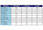
TABLE 1. Outdoor air required.
Compliance Tests
Quick and reliable tests can be employed to identify whether a VRH system has been designed to comply with Standard 62. A reviewer should take a representative sampling of VAV boxes on a system that are used to serve densely occupied spaces. TheVoc for each space served should be computed. The VAV box minimum airflow rates should then be divided by the design outdoor air fraction for the air-handling system to compute the actual outdoor air delivery rate to each space at the critical condition.Provided the design minimum airflows do not exceed the limits imposed by Standard 90.1, the actual delivered outdoor air should equal or exceedVocfor all spaces. If any of the above tests fail, the design probably does not comply with either or both Standard 62 and Standard 90.1, and should be subjected to closer scrutiny.
Conclusions
Throughout this article, the author has made use of the term “classical” when referring to VAV strategies. This was not by accident. “Classical” HVAC systems are configured and controlled for the purpose of providing thermal control of the space. There is little, if any, practical control over ventilation, and they have many systemic inefficiencies. This causes poor air quality and contributes significantly to high levels of energy use. When originally published, ANSI/ASHRAE Standard 62-1989 functionally made classical HVAC systems obsolete.One might be inclined to infer from this article that VAV technology is a dying technology, if not already dead. Such a conclusion would be terribly incorrect. What ANSI/ASHRAE Standard 62.1 and ANSI/ASHRAE/IESNA Standard 90.1 are doing is inexorably pushing the HVAC industry away from obsolete, classical HVAC strategies and pushing the industry toward more efficient, effective and sustainable design strategies.
In a world looking at double-digit energy cost inflation rates, VAV technologies are increasingly important energy conservation tools, and their use should be encouraged. Classical VAV strategies provide energy use reduction through ventilation reduction, which is the underlying cause of their poor ventilation characteristics. The IAQ problems with classical VAV systems are really the result of longstanding strategic misapplications of this important technology. The fact that the HVAC industry has been misusing VAV technology in this manner for the past 50 years should not permit plan reviewers and code authorities to justify or excuse the perpetuation of poor engineering practices.
It is not true that the way the VAV process has been used is the only way it can be used. VAV techniques provide important control and measurement features which will be more appropriately employed in future generations of HVAC systems. We will see VAV strategies evolve to not only address their current deficiencies, but to also add new, important, and exciting capabilities. In addition to improving thermal comfort and control, they are already capable of and will be increasingly used to actively manage ventilation down to the individual room level. This kind of performance has not only been possible with current technologies for several decades, but prototype installations have been in place for much of that time. When properly applied energy recovery technologies replace mixing and recirculation, IAQ issues will disappear and system efficiencies will rise to levels currently believed impossible.
The next level of system above the “classical” will be “transitional” in nature. These strategies will be characterized by the superimposition of dedicated outdoor air ventilation systems onto otherwise classical strategies. These strategies will be characterized by increased installation costs and will leave many systemic inefficiencies unaddressed. This article has provided a glimpse of a transitional strategy in Figure 4.
Part II of this series will discuss the development and advantages behind higher level HVAC strategies. Understanding the limits of classical HVAC strategies is critical to appreciating and understanding the possibilities ahead. The highest level of HVAC systems could be categorized as “fundamentally efficient” and the term high-performance should be reserved for those applications.
These will be typically characterized by a change in the fundamental strategy of HVAC systems away from thermal control toward efficient processing and management of ventilation. These strategies will tend to be custom-developed for each application and will be fundamentally different from all previous HVAC systems. They will be characterized by relatively small capacity requirements, physical simplicity, and lower installed costs. Psychrometrically, they will be highly sophisticated and employ new techniques such as multiple functions, avoidance, and amplification. They will have much lower energy signatures and will be characterized by having no fundamental inefficiencies.
In this last category, this author is aware of at least four high-performance HVAC system strategies which have already been conceived, developed, prototyped, tested, documented, proven, and are ready for mass application.ES
