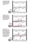
FIGURE 1. Illustration of split system, multi-split system, and VRF system for a small commercial building with four zones (shown in the cooling mode).
What was a primarily residential technology is ready for larger commercial settings. What was
primarily embraced overseas is building momentum in the U.S. This update traces VRF progress, examines some strengths and weaknesses, and spans the globe in an effort to compile some cost comparisons with other alternatives.
Multi-split heat pump systems, using multiple indoor units connected to a single outdoor unit, have evolved from a technology suitable for residential and light commercial buildings to variable refrigerant flow (VRF) systems that can provide efficient space conditioning for large commercial buildings. VRF systems are very popular in Asia and Europe and, with increasing support from major U.S. and Asian manufacturers, the technology is worth considering for multi-zone commercial building applications. VRF technology uses smart integrated controls, VSDs, refrigerant piping, and heat recovery to provide products with attributes that include energy efficiency, flexible operation, ease of installation, and zone control.
This article provides an overview of VRF system technology, including the market situation, technology attributes, performance information, and application recommendations. A future article will address user and utility issues as well as what is holding back the technology, including codes and standards issues, desired technology improvements, and market actions needed to increase penetration of these systems.
Market Position of VRF Systems
Ductless space conditioning products, the forerunner of multi-split and VRF systems, were first introduced in Japan and elsewhere in the 1950s as split systems with single indoor units and outdoor units. These ductless products were designed as quieter, more efficient alternatives to window units (Smith 2007). These units, also known as mini-split systems, have evolved from the earlier products using R-22 refrigerant to those using R-407C, on to current products using R-410A.The progression has been from a few indoor units operating off each outdoor unit to multi-split products with four units to eight units in the late 1980s, then to 16 units in the early 1990s, and to 32 units by 1999.
Current VRF technology using electronically commutated motors, inverter-driven scroll compressors, multiple compressors, versatile configurations, and complex refrigerant and oil circuitry, returns, and controls, can permit as many as 60 or more indoor units to operate off one outdoor unit (Dyer 2006).
Ductless and multi-split products are often considered factory-built systems, competing with traditional unitary products, whereas some VRF manufacturers position their VRF systems as engineered systems that are alternatives to traditional field-applied systems such as chillers. U.S. sales of all ductless, multi-split, and VRF products will be around 250,000 units in 2007.
Sales in Japan (where the VRF concept was developed) and other parts of Asia have been strong. In Europe, where many existing buildings did not have A/C, retrofit opportunities have also created strong demand (Goetzler 2007).
Ductless products entered the market in the U.S. in the early 1980s, but market penetration was minimal, with lack of Japanese manufacturer support infrastructure, and unfamiliarity with the technology holding back sales. Ozone depletion issues became an increasing concern at that time and the issue of a high refrigerant charge of multi-split systems was likely a strong negative for the system. Since that time, refrigerant developments, advances in charge management, controls, and inverter technology have transformed the technology. Asian manufacturers have re-entered the U.S. market individually or in partnership with U.S.-based manufacturers in the past few years to help promote the technology. Less than 10,000 VRF systems will be sold in the U.S. in 2007.
One high-profile signpost for the increasing market acceptance of this technology is the inclusion of multi-split VRF technology with zoned inverter-driven heat pump and heat recovery VRF systems in the renovation of the ASHRAE headquarters building in Atlanta (Johnson 2007).

Figure 2. Major components of a VRF system including the range of possible indoor unit configurations and a typical outdoor unit. (Figure courtesy of Daikin.)
How Does VRF work?
Multi-splits include multiple indoor units connected to a single outdoor unit. Ductless products are fundamentally different from ducted systems in that heat is transferred to or from the space directly by circulating refrigerant to indoor units (evaporators or condensers) located near or within the conditioned space. (When the indoor units are in the cooling mode, they act as evaporators; when they are in the heating mode, they act as condensers.) In contrast, conventional ducted systems transfer heat from the refrigerant to the space by circulating air (in ducted systems) or water (in chillers) throughout the building.VRF systems are enhanced versions of ductless multi-split systems, permitting more indoor units to be connected to each outdoor unit and providing additional features such as simultaneous heating and cooling and heat recovery. VRF heat pump systems permit heating in all of the indoor units, or cooling in all the units, not simultaneous heating and cooling. Heat recovery systems provide simultaneous heating and cooling as well as heat recovery to reduce energy use during the heating season.
Over the past 15 years, the technology has advanced in a number of areas:
- Standard compressors to VFD, inverter-driven scroll compressors
- Direct-driven outdoor fans to VFD, inverter-driven fans
- Direct-driven indoor coil motors to direct current or ECM-type motors
- Variable capacity indoor units
- Better heat exchanger surfaces with multi-segmented coils
- Improved controls and diagnostics
- R-22 to R-410A
- Better refrigerant charge and oil management
Figure 2 shows a single outdoor unit and a general schematic of multiple indoor units in a VRF heat pump system. The indoor units include wall-mounted, floor-mounted, ceiling-cassette, and concealed ducted configurations.
The term VRF refers to the ability of the system to control the amount of refrigerant flowing to each of the evaporators, enabling the use of many evaporators of dif-fering capacities and configurations, individualized comfort control, simultaneous heating and cooling in different zones, and heat recovery from one zone to another. Most VRF condensers use VFDs to control the flow of refrigerant to the evaporators. Refrigerant flow control is the key to many advantages as well as the major technical challenge of VRF systems (Goetzler 2007).
In most cases, two-pipe systems can be used effectively (in VRF heat pump systems) when all the zones in the facility will require cooling or all will require heating during the same operating period. Three-pipe (a heating pipe, a cooling pipe, and a return pipe) systems work best when there is a need for some of the spaces to be cooled and some of them to be heated during the same period. (This often occurs in the winter in medium-sized to large-sized buildings with a substantial core.) One manufacturer has a two-pipe system than can be used to provide simultaneous heating and cooling as well as heat recovery operations.
Heat recovery can be accomplished by transferring heat between the pipes providing refrigerant to the cooling and heating units. One way is to use heat exchangers to extract the superheat from the units in the cooling mode and route it into refrigerant entering a heated zone. One manufacturer sends the refrigerant first to the units that require heating, allows the refrigerant to condense, collects it at a central point, and then sends it to the indoor evaporators to do cooling. Most manufacturers have a proprietary design for heat recovery plumbing and operation with special valving arrangements, heat exchangers, controls, receivers, and distribution boxes.
Ventilation can be integrated with the VRF system in several ways. A dedicated VRF indoor unit could be used in a ducted configuration to condition the ventilation air. A separate ventilation system and conditioning unit could be installed using conventional technology and the VRF system function would be restricted to the recirculation air. Some VRF units have the ability to handle some outside air and could be used accordingly. Bringing the outside air into the room and then conditioning it with the VRF is not recommended except in dry climates where condensation will not create moisture problems. Heat recovery ventilators can be used to reduce cooling loads on the VRF units.
Both water cooled and air cooled systems are available, as well as systems integrated with ice storage units.
What Performance Should I Expect?
Data from a VRF manufacturer compared installation and operating costs for a set of 14 branch buildings in central/northern Italy where a chiller/boiler system was installed in seven of the buildings and a VRF system was installed in the other seven buildings (designed to handle heating down to -20oC [-4oF]) in 1998. The VRF systems used 35% less energy and had 40% lower maintenance costs for the period studied. As suggested by other manufacturers, the equipment costs for the VRF systems were higher than the equipment costs for the chiller-based systems but this was offset by lower installation costs for the VRF systems.Information obtained in discussions with another manufacturer suggests that their VRF systems could save up to 30% to 40% of the energy used by a chiller-based system for a 200-ton cooling system for a generic commercial building. The same data set indicates that the installed cost of a VRF system will be about 8% more than a water cooled chiller and 16% more than an air cooled chiller. Combining these energy use and installed cost projections provides an estimated payback period of about 1.5 years for the VRF compared to an air cooled chiller, and about 8 months compared to a water cooled chiller.
Anecdotal information exists (Rothet al.2002) showing savings of 38% in a side-by-side comparison with a rooftop VAV installation, but this study compared a new VRF system to the existing rooftop VAV system. Simulation results for a Brazilian climate showed savings of over 30% in summer and over 60% in winter. Savings of 5% to 15% were suggested to be more likely in the U.S.
A modeling study conducted with a version of EnergyPlus that was modified to simulate VRF systems showed that, in a 10-story office building in Shanghai, a VRF system saved more than 20% of the energy compared to a VAV system and more than 10% compared to a fancoil plus fresh air system (Zhou et al. 2006).
Installed costs are highly dependent on the application, construction, and layout of the building and whether the installation is new or retrofit. Lack of familiarity with the technology in the U.S will add to VRF costs. Total costs for VRF systems are likely to be about 5% to 20% higher than chilled water systems of similar capacity (Rothet al.2002)
One manufacturer provided verbal information that VRF systems cost about 30% to 50% more than equivalent capacity single-package ducted systems with SEER of 13 to 14. And that VRF systems cost more than twice as much as packaged terminal units. This information is interesting but not as important as the comparisons of VRF and chiller systems if VRF manufacturers position their product as a chiller alternative.
Cost and energy use are highly application-dependent and should be obtained from detailed analysis and corresponding rigorous laboratory and field testing of multi-split systems. The need for this information currently exists for applications in the U.S.
What Are The Best Applications For VRF systems?
Initial applications of VRF in commercial buildings have included building add-ons such as a new data centers and situations where spot cooling is needed. Historical buildings have benefited from the minimum alterations needed for the addition of a VRF system. Retrofit situations where air conditioning may be an addition/upgrade to the space can be good applications of ductless systems since additional ductwork and conditioning needed for ventilation can be minimized with VRF systems compared to ducted systems.Other applications well-suited to VRF systems include anywhere there is an advantage to delivering personalized, compartmentalized comfort conditioning, such as office buildings, strip malls, and hotels and motels. Hospitals and nursing homes can be good candidates as well, since the VRF system makes it easy to avoid zone-to-zone air mixing. Banks have favored the system for security because the egress paths into the bank are minimized due to the minimal smaller diameter ductwork. Even in schools, which often, due to high occupancy, have a 100% outside air requirement, VRF units can be used (often with heat recovery ventilators) to meet the load. VRF systems can also be used in luxury single-family homes as well as in condos and multi-family residential buildings.ES
Sidebar: What About Multi-splits?
Multi-splits offer some of the major advantages of VRF systems such as zoning, capacity control, ease of retrofit, low installation costs, minimizing ducting, and use of secondary fluids and associated costs and losses. On the other hand, their simpler piping results in longer total length of piping compared to VRF systems. Similarly, multi-split heat pumps do not have the opportunity for heat recovery between units that are cooling and units that are heating. As such, multi-split systems should be considered for smaller, simpler buildings where heat recovery is not a possibility and fewer numbers of zones need to be conditioned.REFERENCES
Dyer, Mark, “Approaching 20 years of VRF in the UK,” Modern Building Services, June 2006,http://www.modern-building-services.co.uk/news/fullstory.php/aid/2127/Approaching_20_years_of_VRF_in_the_UK.html.Goetzler, William, “Variable Refrigerant Flow Systems,” ASHRAE Journal, April 2007,http://txspace.tamu.edu/bitstream/1969.1/5546/1/ESL-IC-06-11-80.pdf.
Johnson, Spellman, “ASHRAE Headquarters Building Renovation, Mechanical Systems Narrative,” June 26, 2007,http://images.ashrae.biz/renovation/documents/06js22_mech_design_narrative_permit%20set_2.pdf.
Roth, Kurt, et al. “Energy Consumption Characteristics of Commercial Building HVAC Systems Volume III: Energy Savings Potential,” TIAX LLC for DOE, 2002,http://doas-radiant.psu.edu/DOE_report.pdforwww.eere.energy.gov/buildings/info/documents/pdfs/hvacvolume2finalreport.pdf.
Smith, Lee, “History Lesson: Ductless Has Come a Long Way,” The ACHR News, April 30, 2007.
Zhou, Y., et al. “Module Development And Simulation of The Variable Refrigerant Flow Air Conditioning System Under Cooling Conditions In EnergyPlus,” Texas A&M University, Energy Systems Laboratory, 2006.

 Amarnath is a senior project manager/technical leader in the Energy Utilization program area of the power delivery and markets sector of the Electric Power Research Institute. His research activities also include demand response and dynamic energy management – a dynamic, integrated systems or networked perspective that simultaneously addresses electric energy savings, demand reductions, and peak load management for the industrial, commercial and residential sectors.
  Blatt is an energy utilization consultant based in Mountain View, CA, and has over 30 years experience in commercial building energy efficiency research. His consulting projects have included research on advanced space heating and cooling technology for the DOE, California Energy Commission, and the Electric Power Research Institute. He is an ASHRAE fellow and is active on several ASHRAE Technical Committees.