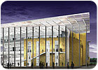
FIGURE 1. Artist’s rendering of the west façade of the Valley Performing Arts Center main lobby.
At first glance, what you see is a fine job with a complex peforming arts center ventilation design. However, cast your eyes a little further around this California campus, and the story gets into fuel cells and sophisticated thermal energy metering. Add the CFD modeling used by the engineers, and you’ve got a thorough design for the auditorium and surrounding spaces deserving of a curtain call.
In the world of HVAC design and construction, there are few building types with as many specific intricacies in the design as higher education performing arts centers. For HVAC designers working on this unique type of facility, there is a mantra: The system has to be quiet. At the same time, it has to be efficient. In the best of designs, it’s both of the above while being essentially invisible, and best yet, inexpensive.
The astute reader will realize that at least one of those points is usually contradictory to the rest. The struggle between the differing needs of performing arts HVAC systems is at times both the biggest challenge in and greatest reward from the design process. Feeling the comfort of a well-designed performing arts center HVAC system while not being able to see or hear it in action is the best reward for the designers of these systems.
This article is a case study of some of the complexities encountered in the design of the Valley Performing Arts Center at California State University, Northridge. The performing arts center project is currently under construction, with an expected completion date of early 2010. Its 168,000 sq ft include a 1,700-seat proscenium theater/concert hall, a 300-person black box studio theater, and support spaces including dressing rooms, green room, scene shop, costume shop, recital spaces, multi-use classroom spaces, administrative offices, and a full campus radio station.
The facility will be erected at the southeast corner of a large, spread out campus, on a prominent corner, as the first building people will see as they approach from the east.
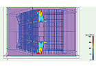
FIGURE 2. CFD result of the tunnel air distribution system under the auditorium.
Careful Consideration
The California State University (Northridge) campus has a pair of interconnected central utility plants, serving buildings with chilled and hot water. While not part of the performing arts center project, the design of the utility plant for the campus is of note in its focus on energy efficiency and sustainability.The chilled water system includes four main chillers located in two different satellite plants on either end of the campus. The chillers supply water to a large chilled water thermal storage tank. During all but the hottest summer days, the entire campus chilled water need is met by the storage capacity from the storage tank. The storage tank is recharged at night, when the campus gets a substantial break in its electric rate from the local utility. To further reduce energy use and operating costs, the campus uses a high (25°F to 30∞) supply-return chilled water temperature differential to minimize the water volume flow rate through the campus, saving both pipe material cost and transport energy.
Maintaining such a high temperature differential presented a design challenge for the performing arts center project. It required unusually careful equipment and coil selections; especially under part load conditions, a high coil temperature differential results in low flow rates that can yield laminar flow conditions within the coil. Laminar water flow within coils has been shown to result in a substantial decrease in heat transfer capacity. A drop-in coil-delivered capacity could result in a loss of control of cooling and dehumidification at part-load conditions, which make up the majority of the hours during the year.
The central hot water utility has also recently undergone an expansion, which focuses on delivering heating water to buildings using sustainable concepts. Part of the sustainable design strategy for the heating water plant included the installation of two hydrogen fuel cells that provide clean electricity to the campus grid. A byproduct of operating fuel cells is a substantial amount of heat that can either be wasted, or, as is the case at this campus, recovered and put to good use.
The full heating and domestic hot water load of the new performing arts center is provided by heat recovery from the fuel cells. Any remaining heat is used in other buildings attached to the central hot water plant. This allows the campus to keep buildings warm without having to engage their large gas-fired boilers for a majority of the year.
Another university requirement for the performing arts center was that the use of both the chilled and hot water in the building had to be billed separately for campus and touring theater uses. To accomplish this, a network of six thermal energy meters was installed in each system. The campus facilities staff will know exactly which portions of the building are using how much energy, and when it’s being used. While this level of monitoring required a $50,000 to $60,000 capital outlay, it is expected to have a simple payback period of less than five years, since it gives facilities staff the ability to trend performance and optimize the operation of the building systems.
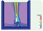
FIGURE 3. CFD velocity profile detail of a seated patron indicating natural convection heat plume.
Designing For Success
Attaching to the central plant was only the beginning of the design process for the performing arts facility. Extensive analysis was performed in the design of the 1,600-seat concert hall and lobby.In the early stages of the conceptual design, it was decided that the concert hall would be designed using a displacement ventilation system with supply air coming out of floor-mounted registers under the occupants’ seats. To deliver supply air to the floor outlets, there are two primary options for a slab-on-grade theater: either buried ductwork or concrete tunnels.
With the substantial rake of the seating in the hall, and the required depth of the foundation system for the orchestra pit, the design was steered toward using concrete tunnels, primarily as a method of controlling costs. Unlike traditional overhead ventilation schemes, which have established rules of thumb and published design guidelines, displacement ventilation systems had not often been used in concert halls in the United States at the time of the design of this facility.
In order to be confident in the design, the mechanical engineering team utilized computational fluid dynamics (CFD) modeling to simulate varying auditorium occupancies and operating scenarios. CFD software allows a user to create a 3-D model of a space that will yield a highly accurate representation of its performance before it is built.
Simply put, you can use the software to not only help design complicated HVAC systems but to troubleshoot them before construction begins. The distribution network is built in concrete, using the building foundations as part of the duct system. The tunnel network followed the stepping of the foundation walls around the orchestra pit, resulting in an arrangement that was too complex to use normal design assumptions.
Instead, the tunnel network was modeled in 3-D and input into the CFD software to determine its performance. Velocity, temperature, and pressure profiles for the entire supply network were developed under varying load and occupancy conditions. Figure 2 shows a plan view of CFD velocity results for the main auditorium floor supply tunnels and under floor plenum.
The final design is a pair of nearly symmetrical tunnels that flanks the sides of the auditorium. The two tunnels discharge into large plenums underneath the main cross aisle in the center of the auditorium. From there, air is routed through smaller air channels and into sub-compartments underneath the seating sections. The entire network of compartments under the seats was designed using CFD in order to maintain even pressure, temperature, and velocity distributions to each of the seating areas so that the auditorium would be uniformly comfortable throughout.
Openings in the walls between compartments were sized using CFD modeling to ensure that no compartment had a velocity in excess of 250 fpm, and no outlet under a patron’s seat exceeded 50 fpm. This is an important criterion to keep in mind when designing HVAC systems using the displacement ventilation concept: at velocities above 50 fpm, most people will complain about drafts from the HVAC system.
Figure 3 is a close-up CFD image of a single seated patron with a diffuser under his seat. It should be noted that the discharge velocity at the grille is below 75 fpm, and reaches 50 fpm before coming into contact with the patron. This image also indicates the plume of flow that rises from the patron due to the buoyancy of the higher temperature air near his body. By manipulating the system variables, the design team worked to achieve comfortable thermal conditions within the occupied zone while using a minimum amount of energy.
CFD is not only useful for displacement ventilation systems, however. In the Valley Performing Arts Center project, the lobby atrium was analyzed using CFD as well. Since the lobby has a west-facing curtain wall approximately 55 ft high, the design team was concerned about maintaining comfortable space temperatures while providing an energy efficient solution for the owner.
Due to the complex nature of the system and the room orientation, traditional calculation methods were not accurate enough. Using CFD, the team was able to analyze the effects of incoming solar radiation, temperature pickup of the building walls, thermal stratification, and both natural and forced convection from the HVAC system. With the use of state-of-the-art design and analysis tools, the design team was able to push the design envelope and deliver a quality project for their client. ES
