
A Higher Ceiling For Higher Learning
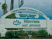
Located in Murietta, CA (less than an hour south of Anaheim), Calvary Chapel Bible College (CCBC) was founded in 1975 as a short, intensive-study program. Throughout its history, CCBC has remained true to its initial vision: to provide a place where serious and committed Christians can learn the Word of God.The college houses 600 students on its 47-acre facility which features a full complement of recreational facilities associated with a resort, including spacious conference rooms, large central meeting rooms, a formal dining room with seating capacity to 700, a grand lobby, and entry rooms.
The college's new 25,000-sq-ft building presents a striking view, yet inside the slab/concrete tilt-up structure, there are plenty of obscured items tied to its HVAC system that have presented striking benefits and savings.
Bucking the Norm
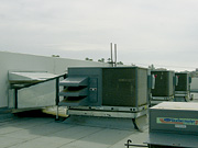
Rooftop units and conventional metal ductwork are construction norms, however, an architect and engineer creatively used an alternative HVAC system that cut installation and construction costs at the chapel by more than $100,000 while also reducing future maintenance expenditures. The chapel features seven 74-ft-long runs of fabric ductwork, each connected to its own respective 12.5-ton, 6,000-cfm cooling/heating rooftop unit in the 12,000-sq-ft gymnasium/chapel.Consulting engineer, Thomas Krusic, P.E., principal, Krusic & Associates (Irvine, CA), and architect, Richard Dayton, principal at Dayton Associates Architects (Newport Beach, CA), chose polyester blended fabric duct because of its superior air dispersion vs. round metal duct. The fabric duct, which is manufactured by DuctSox (Dubuque, IA), uses linear diffusers that the company says supply even and gentle cooling/heating air dispersion along the entire length of the duct vs. registers every 10 ft on round metal duct.
With 39 buildings on the campus, which is the former Hot Springs Resort, Karl Bentz, director of facilities, was an advocate of Krusic's fabric duct proposal because the college had used fabric duct in other previous building projects to save time and materials. More costs in ductwork material were saved because of rooftop placement. Instead of putting rooftop units on the chapel roof, which would have necessitated plenums, elbows, airflow streamlining, and other accessories, equipment was placed on an adjoining portion of the building. This 12,000-sq-ft, L-shaped area of the building has a lower roof that allowed the rooftop units to use horizontal discharge straight through the wall of the chapel at the roof level and into the seven straight runs of fabric.
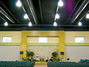
This close collaboration between engineer and architect not only saved HVAC installation time and labor, but also more than $100,000 in building structure costs, according to Dayton. By utilizing the lower and stronger roof of the accompanying building area to support the rooftop units, Dayton was able to incorporate a lighter and less expensive roof design for the chapel. Subsequently, the lighter roof design resulted in a more aesthetically pleasing chapel inside because it didn't require obstructive column supports.
Additionally, Dayton was able to design a higher chapel roof because the parapet, which would have needed a 4-ft height to hide rooftop equipment, was designed for the minimum 12-in. height. Lowering the roof to a code-complying 48 in. below the parapet cap combined with local building height restrictions would have resulted in a lower ceiling that would have affected the chapel's usage capabilities and interior aesthetics.
Accomplished O&M Staff Provides Options
Since the chapel and its accompanying L-shaped building required a total of 135 tons of air conditioning, a chiller, and chilled water circuit was one of Krusic's possible choices of cooling equipment. But because Calvary Chapel's maintenance staff is highly trained on DX rooftop units, Krusic specified rooftop units over a chiller system.Krusic's choice of quantity and capacity of the rooftop units depended upon the weight bearing capacity of Dayton's roof design for the chapel's accompanying building, plus the cooling load mandated by the 15-cfm/person outside air compliance with the State of California's Title 24 "Energy Efficiency Standards for Non-Residential Buildings."
To provide the total 87.5 tons of refrigeration required, Krusic specified seven 12.5-ton 48HJ Series DX cooling/gas-fired heating rooftop units by Carrier Corp. (Syracuse, NY). He had considered a lesser quantity of larger units, but the next step up to 15-ton units in Carrier's 48HJ Series represented a substantial weight load difference per unit that would have necessitated additional roofing support costs.
For mechanical contractor Air Control Systems (Placentia, CA), the connection of the DuctSox to the units was simple. Each unit's horizontal discharge goes directly through the chapel wall where it uses a rectangular-metal-to-round-metal adapter. Then another metal-to-fabric adapter is used to make the transition to the fabric duct runs.
Sound Characteristics Befitting a Chapel
Krusic also found fabric duct to be more sound attenuating than metal duct, which is important for chapel activities. "It appeared to me that the sound attenuating characteristics of fabric duct were more appropriate when the room functioned as a chapel," Krusic noted. Additionally, Bentz and his building committee felt a more subdued ceiling of black DuctSox and painted black ceiling trusses would give chapel room activities prevalence over the building interiors.The absence of a campus-wide BAS prompted Krusic to control the units through the use of thermostatic and time clock controlling based on predetermined setpoints (78°F for cooling, 72° for heating) and chapel occupancy. The rooftops also have economizers, which allow for a minimum setting that's equal to the outside air requirement.
Besides the chapel, Krusic also specified 12 additional smaller rooftops and traditional recessed metal ductwork to accommodate various offices and smaller rooms surrounding the chapel room. Additional rooftop units include 10 3-ton units and two 6-ton units, all from Carrier.
Because of the efficiency, ease of maintenance, and the IAQ achieved in the chapel system, Bentz said future campus building construction and retrofits with open ceiling architecture designs might take a similar approach to the new chapel's design.

‘Chillin' in the Entertainment Center of the World'
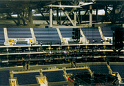
In the city of angels, some of the brightest stars like to be seen, and one place that happens frequently is courtside at Los Angeles Laker games. Yet, no one would want to sit courtside to cheer on Kobe and Shaq if the environment inside the four-year-old Staples Center were too warm or too cold.
Los Angelenos tend to have a rather finicky take on the weather. Just ask Staples Center chief engineer Bill Pottorff. "We've got a bunch of big wimps in this city. If it gets below 65° everybody's got jackets on, and it's just ridiculous," he said.
Fast Build, Not a Fast Break
On October 17, 1999, a rollicking concert by Bruce Springsteen & the E Street Band was the opening event for Staples Center in Los Angeles. Groundbreaking for the new facility had been a scant 18 months earlier. Just a month after the opening, the facilities crew had its first doubleheader sports event, with a need to convert from hockey ice in the afternoon to a basketball court in the evening.
The accelerated construction phase might have been problematic, but Pottorff said extensive planning and an excellent group of contractors and subcontractors worked well as a team to pull off the project. He gave credit to general contractor PCL (Los Angeles) and mechanical contractor ACCO (Los Angeles) for having the HVAC plant up and running under full control by opening night. "Everything had to work right - and it did. Since then we've been fine-tuning the system to maximize efficiency and control."
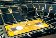
Hardwood to Hard Ice
In a typical season, the facility will have seven to 10 days when there are multiple sporting events on a single day. The hockey ice remains in place all season long and receives an insulated cover when basketball or convention floors are placed over the top. The 35-person facilities crew can change from hockey to basketball, or the reverse, in less than two hours. That includes removing or installing the extra seats used for basketball.The privately owned $375-million facility is adjacent to the Los Angeles Convention Center and is located in the center of downtown Los Angeles. It is the home venue for five professional sports teams - the Lakers and Clippers, the NHL's Kings, the WNBA Sparks, and the Arena Football League Avengers. The facility encompasses approximately one million sq ft and seats 18,500 fans for hockey and 20,000 for basketball.
When the facility was designed, strong emphasis was placed on customer comfort. The seating, sound system, and lighting were all designed to make the spectator experience as comfortable as possible. An essential aspect of the arena is the HVAC system.
Pottorff, who joined the center's staff as the specifications for the HVAC system were being finalized, said he really had only a few things to consider and add at that point. He said he was tempted to specify gas-fired absorbers instead of centrifugal chillers, but a lack of comfort with gas price stability steered him in the direction of the latter. Also, he insisted upon specification of a 300-ton "pony" chiller for after hours or unoccupied hours. Finally, he would have liked to specify an ammonia-based ice rink plant rather than the R-22 plant that was ultimately selected, but local building code prevented the ammonia plant based on its proximity to crowds.
Low-Flow, Low-Temp Design
The consulting mechanical engineer for the facility was M.E. Engineers/Hayakawa Associates (Los Angeles). Their design for the building included a low chilled water temperature, low supply air temperature system featuring high efficiency centrifugal chillers. In the end, three Trane (Tyler, TX) CVHF CenTraVac™, 833-ton, HCFC-123 chillers were specified to deliver water at temperatures as low as 36°.Pottorff said the entire chilled water system was designed to run using glycol if needed, in case colder discharge temperatures were required. "There was concern when we built the place that we might have to run colder discharge temperatures for dehumidification purposes, but we've never had to, and we never will. We already run very cold chilled water temperatures for dehumidification. Discharging that super-cold air off the coils sucks the moisture right out of it," Pottorff noted.
The cooling towers for the units are based on an 82.5° to 94.6° range and operate on a 2.3 gpm/ton flow rate. This comparatively low flow rate helps improve overall system efficiency by reducing pump and fan power requirements over more traditional 3.0 gpm flow rates.
Trane centrifugal chillers supply 42° water to the custom air handlers for most arena events, and they deliver water at 36° for hockey games, thereby ensuring complete dehumidification. The centrifugal chillers deliver chilled water to the air handlers in the range of 40° to 42° during non-ice rink events and at 36° for hockey games and ice rink shows. This lower chilled water temperature during rink events helps ensure maximum dehumidification to help maintain the surface quality of the rink ice. With this low temperature water, supply air is delivered to the space at 40° during ice events and at 45° for other events.
In addition to the centrifugal units, the plant includes the pony chiller Pottorff referred to, a Trane Model RTHC screw chiller rated at 300 tons. The rink ice plant itself consists of 260 tons of CIMCO Refrigeration (Toronto) compressors. Pottorff said the plant, which was specified as a completed package, has performed admirably.
The building's BAS, a Siebe Environmental Controls system (which is now Yamas Controls Group, Inc. [Sacramento, CA]), operates on the OS2 platform. While the system generally meets the needs of the staff, Pottorff said the operating platform has been somewhat limiting.
Sempra Energy Solutions provides 24-hour, seven-day-a-week O&M service for the 2,500-ton cooling plant, 14,000 light fixtures, extensive HVAC and lighting systems control network, and nearly nine miles of chilling coils in the ice floor.
Deep Dehumidification
The air handlers, which are located at the arena's mechanical level, are manufactured by AireSystems™, a Trane custom air handler specialty group. These AHUs feature 12-row chilled water coils. The deep coil design makes these air handlers the principal source for dehumidification of building air, ensuring customer comfort and helping maintain high quality ice for NHL level competition. Other building air handlers include Trane Modular Climate Changer™ and outdoor T-Series™ Climate Changer units. These supply restaurants, sports fan retail areas, locker rooms, office areas, and other administrative spaces.In addition to general seating in the arena bowl, Staples Center features 160 luxury suites. Here, also, the emphasis is on complete comfort and acoustic performance. The suites have individual VAV boxes with electric reheat, with ventilation air provided by a dedicated duct system. An important part of customer health and comfort is adequate ventilation. Staples Center's ventilation system includes a CO2 monitoring and control capability that increases ventilation rates as occupancy levels rise.
Two 228-hp Unilux Boiler Corp. (Woodbridge, ON, Canada) bent-watertube boilers provide the arena's heating needs. At least one of them is fired up each day during the winter, and both units are heavily used during hockey events for additional dehumidification. Additionally, six Ajax hot water heaters provide the facility's domestic hot water needs.
Blowing Smoke
The arena also has a special lightweight (aluminum construction) high-volume fan system for exhausting pyrotechnic smoke. The arena's catwalk system contains 54 exhaust fans and four giant Woods vaneaxial fans. One of those four is dedicated to exhausting pyrotechnic smoke within minutes at 150,000 cfm. This exhaust fan operates at very low sound levels while quickly clearing away smoke residues. It is also tied into the building's Firecom Inc.® (Woodside, NY) fire and life safety system.According to Pottorff, strict attention to acoustic levels is a major aspect of the facility's focus on customer comfort. "We book a wide range of events, not just sports contests. It's important that ambient sound be held as low as possible and that we have good public address acoustics."
Pottorff indicated that the acoustic and comfort performance of the plant has exceeded expectations. "We've had a lot of favorable comments." Hosting events such as the Grammy Awards, the NHL and NBA All-Star Games, and the Democratic National Convention, Staples Center is squarely in the spotlight, and its indoor environment has managed to shine.

Energy Savings Are ‘Bruin'
UCLA, like most major institutions in today's challenging economy, constantly strives to improve efficiency and maintain low operating costs throughout its physical plant. As one of the nation's leading institutions for learning, the university occupies a sprawling campus in the Westwood Village area of Los Angeles. That campus encompasses diverse facilities to educate and sustain more than 37,000 students and 4,000 faculty members.The recent instability and escalation of West Coast energy costs, coupled with extensive maintenance requirements on existing HVAC systems, convinced UCLA's Facilities Management Division to embark on a substantial upgrade of university HVAC installations. The upgrades commenced in July 2000 and are not expected to stop anytime soon, with the dual goals of creating significant utility cost savings and meaningful reductions in O&M expenses.
The school's extensive facility management staff (which includes around 200 people) is constantly working on upgrading HVAC and energy systems. Additionally, the staff is still in the process of repairing damage caused by the 1994 Northridge earthquake.
Joseph Keleman, service engineer for the UCLA facility management, said that the university has committed to keeping facilities as updated as possible, yet meeting the diverse needs of such a huge campus and its staff and students is a daunting task.
VFD Technology Delivers Key Savings
Application of modern AC VFD technology is directly responsible for a considerable portion of the progress being made toward those goals, according to Keleman. From the beginning, GPD 506/P5 VFDs from Yaskawa Electric America, Inc. (New Berlin, WI), were considered an integral part of the upgrade program. "Installation of these high-performance drives was recognized as the cornerstone of our modernization program," said Keleman.Many of the university's existing HVAC components were installed in the 1970s and 80s and utilized a "constant air volume" approach. The fans and motors running at constant maximum speed while the volume of air was modified by a variety of inefficient mechanical devices, such as intake or outlet dampers and vanes, produced some staggering energy costs. In UCLA facilities, as in most, applying 30% to 60% more energy to fan operation than was necessary produced a significant waste of electricity and inflated utility bills.
Preventative maintenance and repair of the vane and damper assemblies was a continuous and expensive operation, Keleman said. "Significant dollars went into maintaining these devices, and into repair of wear and tear on belts, pulleys, and other mechanical components damaged by hard starts and constant operation at 100% of capacity."
"Those factors made the drives very easy to justify through projected energy and maintenance savings and the short payback cycles they generate," Keleman said. The initial AC drive program was undertaken in several campus buildings simultaneously, with an eye to expanding it to facilities throughout the campus. The 30-plus drive installations completed or underway on the university's South Campus include both retrofits and new installations. In addition to Yaskawa, ABB drives have also been specified in a number of campus applications, Keleman said, adding that the latter company's "soft start" feature has played a key role.

Energy Demand Down by 30%
At this point, Keleman estimates that energy demand in areas where drive installation has been completed has been reduced by "at least 30%, and probably much more." Additionally, lower motor speeds are allowing the system to operate more efficiently and reducing equipment wear and tear."The drives also help us cut into our maintenance costs through their ability to deliver ‘soft' starts and stops. Accelerating or decelerating motors and mechanical equipment smoothly cuts down on mechanical stress and wear and tear that occurs when you simply apply line power."
Low operating noise and vibration levels also benefit the people working and studying next to the machine rooms, according to Keleman. "Their dependability, coupled with the elimination of vanes and dampers, has produced meaningful maintenance savings, both in terms of dollars and man-hours expended. We are seeing other benefits as well, including improved temperature control, reduced noise levels, and reductions in peak demand charges."
Keleman presently uses a Siemens APOGEE® serial communications interface for equipment tied into the university's limited BAS. Additionally, a Johnson Controls Metasys® N2 interface is used in several standalone HVAC operations. A planned networking of virtually all AC drives campus-wide into a PC-controlled BAS is, however, on the drawing board. Keleman and the university foresee many additional drive installations in the near future, both within and outside the HVAC area. ES
Smoke Control Design: Fire protection and mechanical engineering must come together to make convention centers and other spaces safe.
By Daniel F. Gemeny, P.E.
The design of smoke control systems in modern buildings oftentimes employs both fire protection engineers and mechanical engineers. Coordination between these two disciplines is essential in implementing a smoke control system into a building. The importance of this relationship has become even more evident over time due to the evolution of fire protection design practices and the emergence of new technologies.
This can be demonstrated in the example of three convention center designs that have occurred during the last 15 years. The Los Angeles Convention Expansion, which began design 15 years ago, relied on smoke control systems for the atrium lobby and the exhibition halls. Smoke control systems were provided as part of an alternate to some of the limiting building code requirements found in Los Angeles. The basis of design for the smoke control systems was 6 ach. The calculation for smoke exhaust was based on a 50% reduction of the total volume of each space, which acted as a large smoke trap. This was seen as an aggressive design solution.
Seven years later, the design of the Anaheim Convention Center Expansion required smoke exhaust systems in the atrium lobby and the exhibition halls. The basis of design for smoke control systems relied on the calculation methods of the Uniform Building Code Section 905 and the ASHRAE Design of Smoke Management Systems. Exhaust rates were calculated with the axisymmetric plume and balcony spill plume equations. The heat release input for these calculations was based on a theoretical boat display fire and fire data for registration kiosks. The design included the use of a fire effects zone model, ASET, which demonstrated that the smoke would be maintained at a height of 10 ft above the highest walking surface in the rooms modeled.
Currently under design, a convention center in a major southwest city will use a CFD-based model fire dynamics simulator (FDS) for modeling, to support the smoke control design. The capabilities of the FDS model will account for turbulence, mixing, and other effects of smoke movement. All floor areas may not remain perfectly clear of smoke 10 ft above the walking surfaces. Therefore, the analysis will need to consider tenability by measuring criteria such as temperature and visibility. Also accounted for will be plug holing and ceiling jet momentum in areas where the smoke layers may be shallow. This type of engineering analysis is part of a performance-based design to evaluate the viability of an exiting system similar to that allowed by code for smoke-protected seating.
This evolution of smoke control design in convention centers is a demonstration of the increasing level of complexity brought to smoke control design. This theoretical complexity may very well contribute to more efficient systems designs. However, it creates ever-increasing challenges to the mechanical engineering team that needs to implement the design into the building. The theoretical solution for the location of exhaust inlets and supply outlets may be unfeasible architecturally or limited by the ability to run the necessary ductwork.
Oftentimes, high exhaust rates in small volume areas require a significant area of supply air openings to maintain the velocity below the 200 fpm maximum. The greater complexity and number of system components increases the potential for individual component and system failure. Therefore, reliability is a significant concern for the mechanical designer.
Even after the design concepts are implemented into the building systems, the completed system must pass rigorous commissioning testing and be maintained throughout the life of the building. Ultimately, the efficacy of the design will likely never be tested in the life of the building due to fire protection efforts and other life safety systems, and this is good. Nonetheless, as technology advances, and the cost-benefits are debated, it is incumbent upon the fire protection engineer and the mechanical engineer to work closely and openly to bring about a well-founded smoke control system design.
Gemeny is vice president of fire technology for Rolf Jensen & Associates, Inc. (RJA) and is located in the Los Angeles area office. A 20-year-plus veteran of the fire protection industry, he is a proponent of performance-based fire protection design and is author of the audio program Performance-Based Fire Protection Design.
