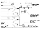
FIGURE 1. An example of a stair pressurization fan with multiple points of injection.
To continue with the smoke control theme, more questions arise, such as: How are exits and atriums kept reasonably smoke-free, and how does all of this tie in with the building system? Also, where does this all end? The answers are not all that difficult, but do take some careful thought, planning, and discussion. As to where does it all end - with a successfully designed and operating building. That is what engineers like to see and be part of: a building that functions correctly, is tested and commissioned, with all issues resolved so we can sleep at night. Now let's look at some more pieces to the design puzzle, as well as stair pressurization and atrium smoke control.
SMOKE-PROOF ENCLOSURES
The 2003 International Building Code (IBC) requires that a smoke-proof enclosure be provided as part of the means of egress, where the building is required to comply with section 403 (High-Rise Buildings) or Section 405 (Underground Building).Section 1019.1.8 of the IBC further requires that each of the exits must be either a smoke-proof enclosure or a pressurized stairway in accordance with Section 909.20. The pressurized stairway alternative is allowed if the building is equipped throughout with an automatic fire sprinkler system. The stair pressurization method is used in health care facilities, which are required to be equipped with automatic sprinkler systems by the Life Safety Code. Most stairways are located internally because climate and related circumstances do not allow the use of open-air balconies separating the stairway (exit) from the building, which would create the smoke-proof enclosure through the open-air vestibule.
Ventilating equipment and systems serving the exit must be independent of other building ventilation systems. Locate the equipment and ductwork on the exterior of the building and connect it directly to the smoke-proof enclosure, or enclose it in a two-hour fire resistance enclosure or barrier. Equipment and ductwork may also be located within the smoke-proof enclosure, with the air intake either located within a two-hour enclosure or installed to receive air directly from the outside. Designers may place equipment and ductwork within the building if separated from the remainder of the building and other equipment by a two-hour, fire-resistance-rated fire barrier (Figure 1.)
Interior exit stairway pressure must reach a minimum of 0.15 in. w.c. and a maximum of 0.35 in. w. c. in the shaft relative to the building, measured with all doors closed. The maximum pressure difference allows doors to be opened by occupants in keeping with the maximum pull force required by other sections of the code.
Ventilating equipment must be activated by smoke detectors installed at each floor level and located as required by NFPA 72. All ventilation equipment and detection systems must be connected to a standby power source, complying with IBC Section 403.10. This equipment must also be suitable for smoke control with defined control and operational sequences.
Pressurization fan air intakes should have a smoke detector installed and wired to the fan start circuit to ensure that smoke from an outside source is not introduced into the stairway. Control of the fan's airflow, in order to maintain the required pressure, can be accomplished with inlet guide vanes or with a VFD.
Suitable fan types include belted vent sets, inline centrifugals, vaneaxial, and other types, depending upon location and space available. Belted fans must have a minimum of two drive belts. Depending upon the height of the stair, multiple points of air injection might be necessary in order to help keep the pressure differences in check.
Determine the maximum amount of required airflow by calculating the minimum required pressure difference across an open door and then assuming that at least four doors would be open: the fire floor, the one above, the one below, and the level of exit discharge. This amount of air can be considerable as one open door can require a minimum of 7,700 cfm, depending upon door width. It is best to always review code requirements, design concepts, and control sequences with the AHJ to gain concurrence prior to document completion.
Acceptance and testing of these systems is required by code and often must be performed in the presence of the building official to confirm the system is operating in compliance with the code requirements as well as with the engineer's design intent. Stair pressurization fan operation needs to be automatic but also under the control of the fire fighters' smoke control panel located in the fire command center. Isolation dampers at the fan inlet, if used, must be able to be fully open within 15 sec (recommended) prior to the fan starting to protect the ductwork.
A sequence of operation for a stair pressurization fan might read as follows:
- Upon initiation of the fire alarm by any means, the stairwell pressurization fan shall start after the motorized damper has been proved open.
- The VFD shall control the fan speed to maintain the pressure with the stairwell between 0.15 in. and 0.35 in.
- The system shall operate in this manner until the fire alarm is reset.
- The fan shall have remote start/stop override located in the fire fighters' smoke control panel located in the fire command center.
- The smoke detector in the fan discharge or in the air intake shall, upon detection of products of combustion, shut down the fan and signal the fire alarm system.
- The fan status shall be monitored by a current-sensing relay and reported to the BAS.
A question then comes to mind. Does the BAS receive a signal from the fire alarm system and control the on/off of the fan and damper operation, or should the fan and damper be directly controlled from a contact in the fan start circuit from a fire alarm signal? Both methods work.
The addressable nature of fire alarm components allows operational control of smoke dampers and fans. Smoke damper operators are either low voltage (24V) or line voltage (120V) with the actual connection usually falling under the fire alarm or electrical contract. For stair pressurization fans, it seems logical to have the fire alarm system control the fan start/stop as the initiating signal is from either a smoke detector or sprinkler waterflow detector. The trend seems to favor having the fire alarm system activate fire safety HVAC components (those not related to building comfort) while the BAS controls the components for comfort and ventilation operation.
Regardless, these systems must be integrated and the operational sequence clearly identified either in the HVAC controls or fire alarm written sequences. The fan electrical control schematic must also match and include the required contacts (N.O. or N.C.) as well as proper references between the two specification divisions (15 and 16), or Divisions 23 and 28 in the 2004 CSI format.
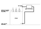
FIGURE 2. An example of the exhaust air and makeup air relationship in an atrium.
ATRIA
Many health care buildings feature an atrium. Atria create openness with inviting atmospheres, meditation, and healing spaces. Special furniture, sculptures, vending, and waiting areas can be contained within the atrium, with functional spaces located at several levels. The atrium floor is generally the egress level, but sloping sites or below grade spaces may require egress paths at more than one level.Atrium spaces are required to be separated from adjacent spaces by a one-hour fire barrier wall. A glass wall forming a smoke partition can be used with proper glass types as long as the glass is protected by a window sprinkler spaced no more than 6-ft apart on both sides of the glass, so that the entire surface of the window is wet upon activation of the sprinkler. According to the IBC, a smoke control system is required in an atrium and shall be designed and installed in accordance with Section 909 of the code.
Large enclosed volumes such as atria may use the exhaust method of smoke removal when accepted by the AHJ. This method requires that the lowest horizontal surface of the accumulating smoke layer be maintained at least 10 ft above the walking surface of the required egress path within the smoke zone.
Provisions for makeup air must be provided either by natural or mechanical means with the limitation that makeup airflow rates shall not exceed 200 fpm toward the fire. Additionally, the temperature of the makeup air must be such that it does not expose temperature sensitive fire protection systems beyond their UL listing or operational limits. This means that fire sprinklers, smoke detectors, and similar items that have lower limits (32°F) and upper temperature limits (120°) must remain functional in a fire situation. Note that actual UL testing temperatures are sometimes different from operational limitations. Cold climate design may require tempering of the makeup air by mechanical means prior to introduction into the space. This could be done using the building air-handling system with 100% outside air or with pretreat makeup air systems using tempering coils.
Air removal usually takes place at the top or uppermost area of the atrium. The type of fan and discharge arrangement is of primary importance. Direct the exhaust plume away from the building with sufficient velocity and height to prevent accidental re-entrainment of smoke into the building or adjacent buildings' air-handling system intakes (Figure 2). Consider prevailing winds during design. Complex sites and buildings may require a wind modeling study to more accurately predict the smoke behavior and determine the exhaust plume height required.
The IBC requires that calculations be performed to identify the "worst" fire location and the resultant amount of air that must be removed to maintain the smoke level at the required height. Plume types are identified in the code, depending upon the space type and overhangs, with formulas to calculate the heat mass flow rates produced by the fire.
Equipment such as fans, ducts, and dampers shall be suitable for the intended use and suitable for the probable exposure temperatures. All belt-driven fans must have a minimum of two belts and be connected to two sources of electrical power - normal and a standby source.
Fire detection systems providing control input or output signals to mechanical smoke control systems shall comply with the requirements of IBC Section 907, which includes references to UL 268 and NFPA 72. Control systems for mechanical smoke control systems must include provisions for verification including positive confirmation of activation, testing, manual override, and the presence of power down-stream of all disconnects and abnormal conditions audibly, visually, and by printed report on a weekly basis. Activation of smoke control systems shall be by automatic means initiated from an appropriately zoned automatic fire sprinkler system, smoke detection system, and from manual controls readily accessible to the fire department.
INTEGRATION
Now, having said all of that, how do all of these systems and components work together? Part 1 of this article identified control sequences and components for various smoke control scenarios including anesthetizing locations and smoke compartment pressurization. These smoke control systems require UL-listed components, such as fire sprinkler heads, water flow alarms and valves, supervisory switches, smoke detectors, fire alarm wiring, fire alarm panels, smoke dampers, and fans.The fire alarm panel must be UL listed for that use and be able to communicate, not only with the field devices, but also with the BAS (HVAC controls). The key is communication and review between the design team, the owner, the contractors, and the enduser. Talk about it all. Have the controls and fire alarm sequences reviewed by someone not directly involved with the project to ensure no holes remain. Meet with the fire alarm and HVAC subcontractors to discuss how they will interface the systems together.
