The affinity laws are most commonly used to derive energy-savings estimates from vsd-controlled devices in comparison with other types of control devices. However, the affinity laws are the frequent subject of debates. The argument is that in an actual situation, the energy savings of a fan or a pump with vsd control are not proportional to the cubic relationship of the speed.
Many individuals argue that it is more of a square relationship, to be conservative. Others would use a 2.x exponent, where 0 = x = 9. The value of x depends on the user, and is often based on the experience of the engineer doing the calculations. There are not hard facts to justify the figure, and there is no consensus on what the exponent should be.

Vsd Variables
The affinity laws were developed for an ideal situation where the Bernoulli equation, and other fluid dynamics equations can be simplified in the following manners:P/w + V2/2g + z1 = Hc (Equation 1)
(Q1 ÷ Q2) = (H1 ÷ H2)2
and (Q1 ÷ Q2) = (W1 ÷ W2)3,
Where
Q = flow;
H = pressure; and
W = power
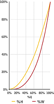
This relationship between these three factors can be visualized in Figure 1.
In most real situations, the formula cannot be simplified. The equation for the pressure remains in the form of H = aQ2 + c (Equation 2), where a minimum pressure c exists along with the following: H1 = aQ12 + c (Equation 3), and H2 = aQ22 + c (Equation 4).
In these situations, (Q1 ÷ Q2) ? (H1 ÷ H2)2, the power equation is: W = HQ ÷ h (Equation 5), where h is the pump-fan efficiency, or W = (aQ3 + cQ ÷ h) (Equation 6).
The power formulae W of a fan-pump is a cubic function of the flow Q. More precisely, it is a third-degree polynomial function of the flow. Any attempt to simplify the formulation in the last equation to W = aQ2.x is wrong and mathematically impossible.
As a reminder, the power equations for a fan and a pump in the in.-lb unit system are:
Equation A
BHP (fan) = (cfm x TSP) ÷ (6,356 x EFF)
or
Equation B
BHP (pump) = (gpm x THD)/(3,960 x EFF).
In terms of percent, Equation 2 can be rewritten as %H = (1 - c')%Q2 + c', where c' is the ratio of the minimum pressure over the maximum design pressure.
For example, in a pumping system where the design pressure is 80 ft and the minimum pressure to maintain is 15 ft, Equation 7 is:
%H = (1 - 15 ÷ 80)%Q2 + (15 ÷ 80),
or
%H = 0.812%Q2 + 0.188 (Equation 8).
The coefficients in Equation 8 are obtained by solving two simultaneous equations with two unknowns. At 100% of the flow, the head is at 100% of the design head, which is 80 ft. At zero flow, the system pressure is at its minimum of 15 ft. The interested reader can go through the exercise to arrive at the coefficients shown in Equation 8.
The power formula is then derived from Equation 6, which is simply:
%W = %Q x %H ÷ h
%W = [(1 - c')%Q3 + c'%Q] ÷ h
(Equation 9).
In an ideal situation, the minimum pressure c' is zero, and the system efficiency h is assumed to be constant for all cases. Under these circumstances, both Equation 7 and Equation 9 can be reduced to the equations of the affinity laws.

Your Results May Vary
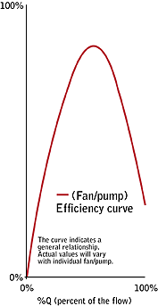
It is possible that there is no minimum pressure required in the system. However, the experienced designer or engineer is aware that the system efficiency of a given fan-pump is dependent of the flow Q. It is unreasonable to expect the efficiency to remain constant at different values of Q.The analogy can be made with the miles per gallon (mpg) ratio of a car, which any driver can relate to. The mpg figure changes, depending on the speed at which the car is travelling. In other words, the system efficiency is never constant, therefore the affinity laws are never applicable in the real world. In fact, they are quite useless and misleading.
The formulation in Equation 9 results in a dimensionless number used to adjust the design Bhp of a fan-pump for any flow situation between 0% and 100% of the design flow. Figure 2 presents a variation of a fan-pump efficiency curve. The actual values of the curve can be obtained from the fan or pump manufacturer.

Efficiency Counts
So far, this article dealt with the motor output in Bhp. To account for the electric input to the motor, additional factors must be considered. The formulation to obtain the kW input to the motor is not simply kW = BHP x 0.746 ÷ EFF(motor) (Equation 10).The drive efficiency and the motor efficiency must be taken into account. The drive efficiency is fairly constant because it has no moving parts. Typically, the drive efficiency is at 97%. However, the motor efficiency is dependent on the load of the motor, which is the ratio of the Bhp calculated of any particular flow Q over the rated hp of the motor. Figure 3 illustrates a typical motor efficiency curve. Thus, the corrected kW input equation is:
kW = (BHP x 0.746) ÷ (0.97 x EFF[motor])
(Equation 11).
The term EFF(motor) is the motor efficiency at the motor loading developed by the flow Q. As can be seen in Figure 3, the motor efficiency is quite poor when the load on the motor is low.
Even if the affinity laws were true (which they are not), they only apply to the power input to the fan or pump. They certainly cannot be applied to the electric power input to the motor providing the motive force to the fan or pump.
