Figure
1.
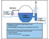
Sight glass and bypass on drum-level application.
Conditions inside steam drums and other high-temperature and pressure applications can raise some real obstacles to true level measurement. Here, the author starts by looking at these impediments and some traditional strategies to compensate for these conditions, and then he suggests some ways guided wave radar and new compensation tactics can combine for consistently accurate readings.
Radar technology in general has been introduced to the process industry as a measurement technology that uses high-frequency electromagnetic waves that are not influenced by the gas phase they travel through or by the temperature and pressure conditions in process vessels. As processes involve more extreme temperatures and pressures, it is time to have a closer look at radar behavior in those critical applications and their solutions and also at the mechanical designs of such measurement devices.
Mechanical Design
Designing a guided-wave radar device or free-space radar device that can withstand extreme conditions is very difficult. It requires know-how of materials and understanding radar behavior in extreme conditions. It also requires know-how to construct a safe and reliable radar that meets the highest industry standards like SIL 2 for both software/algorithm and hardware development (IEC61508) and which is actually proven in use for these extreme application (IEC 61511).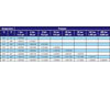
Table
1.
Temperature and pressure effects on the dielectric constant of steam.
Materials
The speed of radar is highly influenced by the impedance of the system it has to travel through or along, so the distance of an antenna to a wall of a bypass or chamber influences the speed of a radar signal. This is true for the mechanical stability and stress of the parts that transport the radar signal from the HF module to the rod/cable or antenna coupling inside a tank or bypass.A simple example is the ceramic used for mechanical stability and isolation material in FMP45, Levelflex-guided wave radar. When one applies 5,800 psi, at 540°F, to that piece of ceramic, the dielectric constant of that ceramic part changes. This change influences the impedance of the system and thus the noise and propagation speed of a radar signal emitted though it.

Figure
2.
Boiler-level control.
Radar Signals
All radar technologies on the market that are used to measure level use the “time of flight” principle. This means the device measures the elapsed time between emitting and receiving a pulse consisting of a bundle of high-frequency electromagnetic waves. The frequencies of the waves vary between 1 GHz for guided wave devices and 6 to 26 GHz for free space radars.Speed of Radar Signals
Radar signals travel at the speed of light in a vacuum. This speed varies outside a vacuum. The pressure and temperature of a specific gas phase or liquid also influences the speed of radar signals. The extent of this influence depends on how polarized the gas is - in other words, how much the dielectric constant of the gas phase varies due to temperature or pressure changes in the application. Hydrocarbon vapors show little change even under high-temperature or high-pressure process conditions, but high polar steam does. The dielectric constant of steam at 212°F is 1.005806. But at 691°F, it is already 3.086.Steam System Applications
There are several critical boiler system control points, with the primary one being the boiler level control. The second is the level control of the feed water to the boiler and the condensate return level.Boiler level control. In a typical steam application, the level of the water in a boiler is of utmost importance. Radar measurement devices are used more and more in these critical applications. They offer advanced diagnostics and insensitivity to build-up and temperature fluctuations that bother other measurement systems, such as those that use differential pressure devices and displacers. Both use the “density” of the product to determine the level, but the density of water changes significantly enough in a boiler system to lead potentially to large measurement errors between the “real” level in the boiler and the measured value.

Figure
3.
Reference rod located in the gas area.
Boiler feed water control and condensate return. The surface of a receiving tank for condensate return can be turbulent. This not only makes it difficult to measure with free space radar, but it also leads to issues regarding changing radar speeds and also condensation on the free-space radar antenna. It is not simple to use differential pressure in these applications. There can be large temperature shocks, especially during the start-up phase of a boiler system. Furthermore, the density of the liquid can change over temperature, leading to large measurement errors. A much more reliable system is a guided-wave radar device with gas-phase compensation in a co-ax pipe.
Steam: a Difficult Medium
Steam is a highly polar gas, which means that the speed of radar signals in high pressure and temperature steam applications may be reduced. In a boiler, for instance, this leads to a lower-than-actual water level reading. This can be dangerous, influencing the performance of boilers and causing a reduction in the quality of steam. This error can easily be as large as 30% to 40%, depending on the pressure and temperature of the steam and distance from the launch of the signal to the actual water level.Process Changes and Radar Speed
The simplest (but not the best) way to overcome the effects of process changes on radar speed is to input the temperature or pressure and have the radar unit calculate the “offset.” The method will cause large errors during the start-up of an installation. Normal operating conditions have not yet been met, and thus the unit will overcompensate. One could also program a compensation table in a DCS or PLC and connect this to a pressure or temperature transmitter.
Figure
4.
Dynamic gas-phase compensation.
