
FIGURE 1. Ten-foot wall-mounted canopy hood test setup with heavy-duty charbroilers(note transparent back wall).
When is listed cfm not an adequate criterion for selecting a kitchen hood exhaust system? Well, just about always. Where is the hood located? Does it use side panels? Any other diffusers or ventilation equipment nearby? And how are those listing tests conducted, anyway? Read on to clear the air and avoid getting grilled about trouble in one of your kitchen applications.
Hot air rises, and an exhaust fan in the ceiling could easily remove the heat produced by the cooking equipment. But mix in smoke, volatile organic compounds, grease particles, vapor from cooking, and combustion products, and you have a need for a means to capture and contain the effluent to avoid health and fire hazards. While an exhaust hood and its system components serve this purpose, the key question is always, “What is the appropriate design exhaust rate?” The answer always depends on four factors:
- The type, energy source, and use of the cooking equipment below the hood
- The position of this cooking equipment below the hood
- The style and geometry of the hood itself
- How the makeup air (conditioned or otherwise) is introduced into the kitchen

FIGURE 2. Hood setup with and without side panels.
“Hood capture and containment” is defined by ASTM F1704-05, “Capture and containment performance of commercial kitchen exhaust ventilation systems,” as “the ability of the hood to capture and contain grease laden cooking vapors, convective heat and other products of cooking processes.” Hood capture refers to the products getting into the hood reservoir, while containment refers to these products staying in the hood reservoir and not spilling out into the space. “Minimum capture and containment” is defined as “the conditions of hood operation at which the exhaust flow rate is just sufficient to capture and contain the products generated by the appliance in idle and heavy load cooking conditions, or at any intermediate prescribed load condition.”
Pacific Gas & Electric’s (PG&E) Food Service Technology Center (FSTC) undertook an evaluation of wall-mounted canopy hoods from several different manufacturers in accordance with the ASTM 1704 test method. This testing was conducted at the Commercial Kitchen Ventilation (CKV) Laboratory in Wood Dale, IL, with a generic unlisted hood included in the test matrix. Each wall-mounted hood was 10 ft long and was tested over standardized cooking equipment, including a heavy-duty, medium-duty, light-duty, and mixed-duty product line. The primary tools used for airflow visualization were schlieren and shadow graph systems, which visualize the refraction of light due to air density changes.
Since the heat and effluent generated by the cooking process change the air density above the equipment, the system provides an image of the thermal activity along the perimeter of the hood, confirming capture or documenting spillage. By increasing or decreasing the airflow rate, the threshold of capture and containment (C&C) was determined. For this hood performance investigation, the replacement air was supplied from low-velocity, floor-mounted displacement diffusers along the opposite wall. Test results for the individual hoods can be downloaded from the FSTC website athttp://www.fishnick.com/publications/appliancereports/hoods/.
Figure 1 shows the test setup for a wall-mounted canopy hood over three heavy-duty charbroilers. Note that the back wall is transparent to permit the light from the schlieren system to pass through. Figure 2 illustrates the hood setup with and without the partial side panels. The results of this heavy-duty appliance challenge are shown in Figure 3 for four models of listed hoods and one unlisted hood.
Testing was conducted with the appliances pushed as far back (towards the back wall) as possible to maximize the overhang and minimize the rear gap, both positive attributes for optimum hood performance. For one test in the “no-side panel” configuration, the generic hood was pulled forward until the overhang was only 6 in. In this case, the C&C rate increased dramatically.
For all hoods, the C&C rate decreased when partial side panels were installed. The threshold of C&C decreased even further when the gap between the back of the appliances and the wall was flashed in with sheet metal. For reference, the exhaust requirement for an unlisted hood from ASHRAE Standard 154-2003, “Ventilation for Commercial cooking Operations,” is shown as a solid line at the 400 cfm/ft mark. This also matches the requirement in the International Mechanical Code (IMC) for an unlisted hood.
As illustrated, all of the listed hoods were able to capture and contain the cooking effluent at significantly lower airflow rates. Adding partial side panels and sealing the gap between the appliance and wall resulted in an even greater reduction in the airflow needed for total capture of the effluent under full-load cooking. Note that the values shown are the threshold of C&C under ideal conditions of makeup air supply and no intrusion from staff walking along the cook line. A design value needs to include a safety factor to accommodate for the dynamics of the kitchen environment.
Listed Exhaust Hoods and The Fallacy Behind The ‘CFM' Ratings
There is often an underlying supposition that the exhaust hood will function satisfactorily if it is specified in accordance with its UL-listed airflow capacity. This may be far from reality.For example, a heavy-duty appliance such as a charbroiler at the end of a mixed-duty appliance line is going to require a design exhaust ventilation rate (based on the experience of the author and data shown in Figure 3) of at least 300 cfm/ft for a wall-mounted canopy hood (depending on the actual hood being specified). If side panels are utilized, and overhang is maximized, this design number might be dropped to 250 cfm/ft.
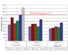
FIGURE 3. Wall-mounted canopy test results with heavy-duty charbroilers. (CB/CB/CB stands for three charbroilers under full-load cooking.)
To fully grasp this predicament, one needs to understand how a listing agency conducts their capture and containment (smoke and flare-up) test in accordance with UL 710. For the case of a high-temperature (600) application (which would apply to a hood over a heavy-duty gas charbroiler), the minimum and maximum length of a given hood model is tested over an electric broiler (with cooking surface dimensions less than 2 ft x 2 ft). This electric broiler (or maybe an electric griddle with its thermostat cranked up), is installed at one end of the test hood. The exhaust rate is increased until no visual smoke is perceived to spill while the broiler is cooking a full load of 30% fat hamburger patties. The exhaust rate under this capture condition becomes the reported minimum cfm within the hood’s listing.
Now, anybody in the foodservice industry understands that a 2 ft x 2 ft electric broiler does not produce the equivalent heat and smoke of a commercial gas charbroiler, with dimensions that would typically be 2 ft x 3 ft or 2 ft x 4 ft and have rated inputs in the range of 100,000 to 140,000 Btuh. It becomes obvious that a hood may not be able to capture the heat and smoke produced by a gas broiler if the exhaust hood is sized according to its minimum “cfm” listing for a 600 classification based on the smaller electric broiler.
Taking a more optimistic perspective, the exhaust rate required to ventilate a mixed-duty appliance line (typical of an institutional kitchen with a range top, broiler, fryer, steamer, and oven) may be closer to the average of the ventilation requirement for the individual appliances. Since codes dictate that the exhaust airflow be based on the heaviest duty appliance under the hood, a hood installed over a mixed-duty appliance line may work OK if it is sized based on the hood’s listed cfm for a 600 application. But if the broiler is placed at the end of the cookline and side panels are not utilized, the capture and containment performance will be compromised. Add in a four-way diffuser near the hood, and the situation goes from bad to worse and the phone starts to ring.
Take-Home Tactic
There is a silver lining within this cloud of concern about the listed cfm. The fact that listed hoods have been rated at airflows that are well below the prescriptive requirements for unlisted hoods allows the designer to select an effective exhaust flow rate that is in between the two cfm numbers. Rather than gambling on the listed exhaust rate, the designer should utilize hood manufacturers’ software or calculations to select an appropriate design value for a given project. And one last bit of advice. Hold “spec” on the design exhaust cfm; it should not be negotiable within the competitive bid and the consideration of alternative ventilation system proposals that are put forward based on lower listed cfm values. Consider specifying exhaust airflow performance based on the ASTM 1704 test protocol.Once you have spec’d out what you think is the best hood for the project, remember the ability of that exhaust hood to C&C the effluent produced by the cooking equipment is a function of much more than the physical attributes of the hood.
Unfortunately, many of these influencing factors are overlooked in the detailed specifications (e.g., appliance positioning beneath the hood or the delivery path of the replacement air). Beneficial design factors, such as overhang, hood height, side panels, or end walls may be downplayed in terms of their significance and neglected within the specifications. Specifying a top-of-the-line exhaust hood is important, but it is only the first step in designing a high-performance kitchen ventilation system.
