Control of humidity in a critical environment is as important to ensuring reliability as temperature control, yet is often ignored until it's too late. Low humidity can lead to static damage. High humidity can lead to degradation of electronic equipment and swelling or delamination of printed circuit boards (PCBs). The result will be equipment failure and reduced up-time.
There are many approaches to controlling humidity in a data center. The first decision is where to control it from, e.g., at the local computer room air conditioning (CRAC) units or centrally at the makeup/pressurization AHUs. Consideration must then be given to the type of humidification system to use. Spray pads, ultrasonic, steam, and infrared systems have all been used in critical applications with varying degrees of success.
One of the most important factors in regulating humidity is proper sealing of the room and installation of an appropriate vapor barrier. Without a vapor barrier, it may be nearly impossible to add or remove enough moisture to precisely control the interior environment. This article will examine all of the above, plus control schemes, safeties, and lessons learned.
WHY CONTROL HUMIDITY?
There are many data centers with no independent control over humidity. Do they function? Yes. Are they at risk? Definitely. Can we quantify the risks? Let's see.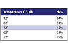
NORMAL CONDITIONS
Let's start with a look at the range of humidity conditions that may occur in the data center environment and how humidity is measured. Humidity is a measure of the amount of water vapor in the air. The common measures of humidity are relative, specific, and absolute.Absolute humidity is a measure of the actual mass of water vapor in an air/water vapor mixture, (lbwater). Specific humidity (or humidity ratio) is the ratio between the actual mass of water vapor present in moist air - to the mass of the dry air (lbwater / lbdry-air). Rh can be expressed by partial vapor and air pressure (pw / pws), density of the vapor and air, or by the actual mass of the vapor and air, and is usually expressed in percent(%) .
Rh can be expressed as the ratio of the vapor pressure of the air to the saturation vapor pressure of the air at the actual dry bulb temperature. That is, at any given temperature the rh is the ratio of water vapor in the air to the maximum amount of water vapor that the air can hold. If the rh is 0% there is no water vapor. If the rh is 100%, the air can hold no more water, at that temperature, it is saturated. This is important to consider when analyzing the consequences of rapid temperature changes and consequent humidity changes that can occur during non-normal conditions. Those will be discussed later. Generally, people are comfortable in the 25% to 60% rh range.
A related term is dewpoint, which is the temperature at which water vapor starts to condense out of the air; the temperature at which air becomes completely saturated. Above this temperature the moisture will stay in the air. On a psychrometric chart, this temperature can be read by following a horizontal line from the state-point to the saturation line. Dewpoint is represented along the 100% rh line in a psychrometric chart.
Table 1 shows the changes in rh as a function of temperature for a fixed absolute humidity. Our baseline will be the typical data center space conditions of 72°F db and 45% rh. The specific humidity at this condition is 0.077 lbwater / lbdry-air (54 grains/ lbdry-air). The dewpoint at these conditions is 50°.
CONSEQUENCES OF LOW HUMIDITY
By definition, static electricity is an electrical charge at rest. The discharge of this built-up energy can cause numerous problems. When the humidity is low, static electricity is high. How much static electricity is too much? A charge of 3,500 to -4,000 V sounds like a lot, but it is actually the minimum a person can feel. (Remember high school physics? Static voltage isn't life threatening because the amperage is tiny. It's amps, not volts, which are dangerous.). According to industry sources, a static charge as low as 400 V can cause non-catastrophic damage to integrated circuits. Table 2 shows how much static electricity can be generated by various activities at different humidity levels.Conditions that can result in static charge build-up are ungrounded raised floor pedestals, carpeted tiles with low natural fiber counts (specified static electricity build-up should not exceed 2,000 V at 40% rh), using chairs with plastic or vinyl seats, chairs or equipment carts with casters, and failure to use wrist straps when working on equipment.
Today's electronic equipment has a dense geometry, and is composed of thin, easily damaged materials. Damage caused by electrostatic discharge (ESD) can take the form of catastrophic failures, but is more often low-grade damage that may not show up during initial setup, but can make equipment more susceptible to a later failure. Cumulative degradation of the components can also occur as the result of repeated, low-voltage exposures. These types of problems are very subtle and extremely difficult to detect. One complication with assessing static damage is that the results are not always immediately obvious because the resulting failure often destroys the evidence of damage. It is often problematic to state categorically that a failure was caused by static damage.
While humidification does increase the surface conductivity of the material, the charge will dissipate only if there is a conductive path to ground. Surface resistivity of many materials can be controlled by the humidity of the surroundings. At a humidity of 40% and higher, the surface of most materials will adsorb enough moisture to ensure a surface conductivity that is sufficient to prevent accumulation of static electricity.
When humidity falls below about 30%, these same materials could become good insulators, in which case accumulation of charge would increase. Control of humidity is the easiest and surest way of mitigating build-up of static electricity.
CONSEQUENCES OF HIGH HUMIDITY
In the electronic industry, printed wirings get corroded due to presence of high humidity. Transistors may break down or suffer a decrease in longevity.When the air temperature is lowered below the dewpoint temperature, water condensation is formed. An ideal condition for condensation to occur would be in a data center where the air is maintained at 72°, but the outside environmental conditions are 90° with about 90% rh (hot and humid). Introduction of this unconditioned air can produce condensation. The results of condensation inside an electronics unit can be degraded equipment performance, specifically:
- Changes in surface resistivity that alter timing circuits, change the frequency of oscillator circuits, change the current level in a constant current source, result in loss of sensitivity or reduce the input impedance on high impedance amplifiers.
- Electrical shorts
- Swelling and binding of mechanical moving parts
- Localized corrosion
- Delamination of PCB materials
- For facilities with older raised floor tiles where galvanic coatings were used, high humidity can cause the formation of a zinc solute, which can lead to the growth of zinc whiskers (filamentary growth on metallic materials) on PCBs. Whiskers can grow long enough to short out circuitry.
CONTROLLING HUMIDITY
By now the need for humidity control is clear. Our next decision is from where to control humidity. There are pros and cons to both local and remote control of humidification. Many engineers, owners, and operators have experience with various configurations and systems and have strong opinions for and against.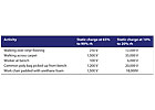
LOCAL VS. REMOTE
If a facility has a dedicated makeup air/pressurization unit with a redundant backup, the incremental cost for adding humidification and reheat (for dehumidification) is marginal. Remote control of humidification offers the advantages of running city water piping to one or two locations as opposed to CRAC units throughout the raised floor. Additionally, there is a significant cost savings for running smaller power circuits to each CRAC unit (no humidifier or reheat). These two items are particularly important considering the increases in the cost of copper in the past year.
For facilities where CRAC units are DX and no water is allowed on the floor, the choice is obvious; humidity must be added remotely. For small facilities, facilities where there are no dedicated makeup air/pressurization units, the choice is also clear. Add humidifiers and reheat to the CRAC units. For facilities served from central station air handlers (no local CRAC units), humidification should be installed in the units.
TYPES OF HUMIDIFIERS
Several types of humidifiers have been in common use in critical environments over the years. Table 3 shows a comparison of various systems.Spray pads are used on large air-handling systems and have developed a poor reputation for several reasons. The nozzles require periodic replacement and the water often sprays other than where intended. The spray pads need frequent replacement. The collection basin is a potential sanitation problem and the water spray is often wasteful and excess unvaporized water and resultant scale and sediment are sources of corrosion and potentially encourage organic growth.
Ultrasonic humidifiers use a Piezoelectric transducer that converts a high frequency electronic signal into high frequency mechanical oscillation, which ultimately converts water into vapor at low temperature and pressure. They generate a mist with a particle size 1/50th the size from a spray nozzle. They generate no waste water. Operating costs are on the order of 1/10th the cost of operating an electric steam unit. They can be installed in makeup AHUs, in the supply ductwork, or in individual CRAC units. Ultrasonic humidifiers should only be used with deionized water and an RO water treatment system is recommended for most installations. The high maintenance attention rating is due to the care RO system needs and the 3- to5-yr life of the ultrasonic transducers. Both spray pads and ultrasonic humidifiers drop the supply air temperature because the vaporization of the droplets draws heat.
Electric steam humidifiers, sometimes called electrode humidifiers, boil water in a canister to generate steam that is delivered through a perforated tube. The tubes are installed in supply ducts or in CRAC units. They can also be installed in air handlers. It takes time for the canister to boil and response to changing conditions interior environmental conditions can be slow. Local water should have a conductivity of 200 -to 500 micromhos for reliable operation; deionized water will not work. Steam canisters require periodic replacement and should not all be replaced at once or during times of high demand, since the canisters need to run about 24 hrs before they produce at full output (the addition of salt speeds the process).
Infrared or quartz humidifiers use high intensity quartz infrared lamps over a stainless steel humidifier pan. They are active in about 6 sec and are typically installed inside CRAC units and sometimes in smaller central AHUs. Lamps on infrared humidifiers need to be replaced regularly and the pans need to be descaled periodically to remove mineral deposits. Also, the sockets occasionally require replacement. Infrared and steam systems add some heat to the airstream.
Electric and infrared may be good choices where electricity costs are low and keeping first cost down is important. Though not listed, direct steam may be a good choice, if available. When evaluating humidification systems, investigate local utilities for rebates for installing the lower energy consuming ultrasonic systems in lieu of the electric steam or infrared systems.
OTHER DESIGN CONSIDERATIONS
Correct system sizing is important, particularly on makeup air and units with return air. Compare 100% air outside air (OA) conditions on a clear, dry 55° day with mixed air conditions at minimum OA on winter design day to determine maximum humidification requirements. Also, consider the cooling effects of ultrasonic systems when determining the highest humidification requirement (humidification system size can be reduced on mixed air units). Set the discharge temperature at 70° (or higher if necessary, with a good PID loop) for units that are for pressurization, not cooling; the air can hold more moisture.CRAC units are typically sensible coolers and are selected for little or no latent cooling. In this case a rule of thumb is to provide 25% of the units with humidifiers. This will work if a vapor barrier is installed, however, if the facility operators change the temperature and humidity setpoints (or lower the chilled water supply temperature), the CRAC unit coils may be doing more dehumidification than the design allowed for, and more humidifiers may be required to meet demand.
Proper installation per manufacturer's instructions, particularly with regard to velocity and straight runs if installed in ductwork, is essential to success. Steam electrode systems and infrared systems installed in CRAC units generally perform reliably. Ultrasonic systems in CRAC units have had some difficulties due to placement and are less common.
DEHUMIDIFICATION
Dehumidification is a simpler issue, but is given far less attention. Dehumidification is simply subcooling the air to remove moisture and then reheating it as required to maintain space temperature. In a central system, provide a reheat coil and program a dehumidification sequence into the control logic. If the choice to control humidity is at the CRAC unit, then add a reheat coil, enable the dehumidification cycle, and control for absolute humidity. For chilled water units, the chilled water temperature must be low enough to allow dehumidification. Reheat coils are necessary to prevent overcooling the floor, particularly at low load conditions. For makeup air units, the summer discharge temperature should be 55° and reheat is not required.VAPOR BARRIERS
Pressurization has no impact on humidity control. Installation of a vapor barrier is necessary for any humidity control system to function properly. A vapor barrier is any material, usually a plastic or foil sheet, that resists passage of both air and moisture through walls, ceilings, and floors. They are usually made out of plastic, such as polyethylene. Whatever material is used, it must have a permeability rating of 1 or lower. Aluminum foil is virtually impervious to water, with a permeability of 0.0001. Polyethylene plastic sheet, 6 mil or greater in thickness has a permeability of 0.06. Additionally, some paint manufacturers are producing a vapor barrier primer suitable for new or previously painted gypsum wall board with a permeability claim of 0.5.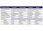
IN THE DATA CENTER
Insulation and a vapor barrier should be applied to both interior partitions and exterior walls if there is a temperature or humidity difference between these areas. A vapor barrier must be continuous to work properly. Seams should be sealed. There should be no tears, and electrical receptacles and switches, and locations where walls meet ceilings and floors should all be sealed.Analyze the conditions of adjacent spaces and you may find a need to apply a vapor barrier at the ceiling as well. In existing facilities, it may be more cost effective to apply a vapor barrier paint than new insulation with a vapor barrier and new gypsum wall board. Carefully analyze the existing wall construction and outside conditions to determine where the dewpoint will occur and what the consequences may be. What is suitable for a 12-in. concrete wall in a moderate climate may result in wet fiberglass in other construction types and climates. Another recent alternative, particularly useful for interior walls, is foil-backed gypsum wall board. Again, pay attention to sealing joints. Taping a 12-in. wide polyethylene sheet at each joint has proven successful.
Doors are always a source of leakage. The best solution is weather-stripping. Typically, a data center does not have windows. If there are windows, and they are to be blocked off, certain precautions must be taken. Airflow must be allowed to circulate around the interior side of the window; otherwise the glass is subject to thermal stress cracking and the interstitial space between the glazing and block-off barrier will develop condensation. Drilling holes in the covering board at the top and bottom of the window allows air to circulate and ameliorates the situation.
THE SOLUTION
Proper control of data center humidity will improve reliability, availability, and up-time. Ignore humidity and the facility remains at risk. It's that simple.EDITOR'S NOTE: This is an extended version of the article that appeared in the print version of ES.
