Imagine a tool that will make you more confident that you have a better design for laboratories with fume hoods – before they are built. Or a technique to see the results of your design, before it’s constructed, with astounding accuracy. Computational fluid dynamics (CFD), an efficient analytical tool to aid in the design of fume hoods and laboratories, provides this.
What CFD Does
CFD provides airflow modeling inside and outside of laboratory facilities. Studies focus on the flow of ventilation air as it affects air quality, temperature, pressure, comfort, and the migration of airborne particles or gaseous contamination. Output from CFD helps designers plan optimum fume hood and ventilation systems in laboratory facilities. It is also useful for exterior wind wake analyses of chimneys and exhaust vents.The software is based upon relationships known as the Navier-Stokes equation: highly complex, non-linear differential equations that represent the movement of fluid or gas through three-dimensional space. Although the Navier-Stokes equation is more than 100 years old, the technique did not become useful until the late 1960s when powerful computers made the application practical.
The CFD method works by dicing up a problem into imaginary cubes of fluid or gas, applying the Navier-Stokes equations to each of the cubes, balancing the mass, momentum, and energy between them, and then reassembling the collective behavior of all the cubes back into the original problem. In any given project, the number of imaginary cubes, or cells, is routinely between 50,000 to 200,000, but it often extends up to 600,000 to 800,000 cells. Each cell usually has seven degrees of freedom (DOF) associated with its behavior. The DOFs are typically pressure, temperature, velocities in three dimensions, and two turbulence terms. The cells can also have additional terms such as secondary species concentrations, or kinetic reaction equations.
Early CFD analyses were performed in only two dimensions to conserve memory space and were notorious for producing reams of numerical data readable only to the most dedicated scientists or engineers. Today, with minicomputers, workstations, and desktop PCs, highly complex CFD problems may be solved quickly and at a small fraction of the cost of early analyses. Additionally, the CFD codes of today include spectacular graphics which display the output in a multitude of ways that even the most casual observers can understand.
CFD in Action
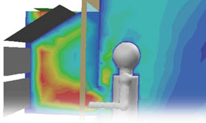
As an example of how CFD may be used in a practical design setting, a simple laboratory with five fume hoods is selected using two sash opening heights. The intent is to show the typical types of output available from CFD and also how a simple change in the sash opening can cause a small breech in containment. Below are several figures of a typical medicinal chemistry lab with five fume hoods and a central bank of laminar flow supply diffusers.
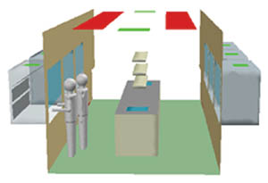
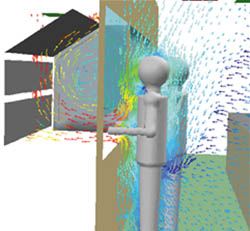
Figure 1 depicts the overall geometry of the room with the fume hoods at a one foot sash opening, two human figures, a large bench with two sinks, shelving, and a second bench at the end of the room. Air is supplied above the bench area and flows from the ceiling toward the bench. When the air reaches the bench, it splits and flows toward the fume hoods.
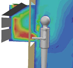


In some non-critical cases, the breech may be acceptable, such as when the chemicals used in the fume hood are largely nonpoisonous or if the fume hood is used for purposes other than containing toxic compounds. In most cases, however, the breech would be unacceptable and would require immediate engineering attention. The following section describes how one would address this problem and how an integrated engineering team approach can develop a solution.
When CFD analysis is applied to a project such as a lab with fume hoods, there are several typical steps that the analyst must take prior to producing final results.
Outline Requirements
Inputs about the lab’s size, shape, airflow rates, temperatures, etc. must be collected as boundary conditions to a CFD model. The inputs must also include the limitations of the lab design and other requirements that the enduser may have. For example, the lab may be a retrofit with a ceiling that can only be nine ft high and does not offer the possibility to punch new supply ducts from directly above.Analyze space needs. Understand the space you have and need for your laboratory. Are you renovating an existing facility? Are you planning new construction? What is your estimated volume of space? The more the CFD engineer knows about the constraints of the lab, the more likely it is that they will be able to provide the optimum ventilation scheme at the minimum energy consumption.
Preliminary hvac design. Complete a preliminary lab design using conventional wisdom for the hvac layout and guidelines such as the ASHRAE Standard 110 for fume hoods. This is where teamwork between the CFD engineer and the hvac engineer is most important.
CFD parametric analysis. Complete an initial CFD analysis for the preliminary design and then evaluate several typical variations to the operating conditions such as sash opening heights, room supply rates, effects of people walking by the fume hood, doors suddenly opening into the lab, and power outages. This parametric CFD analysis, which creates a “performance envelope,” evaluates the entire environment of your laboratory, including factors ordinarily very difficult to evaluate prior to construction and installation. Because of the graphical nature of the CFD output, you will see many aspects of airflow behavior, contaminate concentrations and temperatures at all points in the environment.
Design feedback. Identify the strengths and weaknesses of your lab design, and alter as necessary. Here is where combined experience of CFD and hvac design is necessary to make the whole process work. Constant feedback between experienced CFD and hvac design professionals can result in a system that “works” before it is built. Our experience has been that a properly conducted CFD analysis – when followed by accurate and well-supervised construction of what was designed – results in a facility that performs almost identically to CFD’s predictions. Usually, only two or three iterations are required to optimize the ventilation performance of the preliminary lab design using CFD.
Physically test if required. After construction, follow up with an appropriate experimental physical test, such as the ASHRAE Standard 110, if required.
Verify hvac operational conditions. Verify that the hvac operational conditions are as modeled, including supply rates, inlet temperatures, and the size of the laboratory. Also, be sure that the “as-modeled” conditions of supply, exhaust, and temperature control are written into the operating protocol for the building.
Typical Problems
“You get what you ask for.”Important but often overlooked: after the CFD modeling, you must follow through with your contractor to make sure you get what you designed. This can be done through your architect, engineer, or construction manager. There have been documented cases where laboratories did not function as designed, even after using CFD analysis. Upon investigation, the cause was usually a function of construction not meeting the specifications laid out by the CFD engineer and dictated by the architect. Often, either:
- The location of the supplies was not accurately placed as shown on the drawings.
- The airflow rate delivered by the supply was incorrectly set.
- The balance between the supplies and returns fell out of its specified range.
“I Used CFD Once, and it Didn’t Work …”
Today, there are many examples of how CFD has been used accurately and successfully to affect the designs of a wide array of buildings or products. As an example, the Boeing 777® was completely designed on computers with a minimum of testing. The CFD portion of the design study was used to optimize aerodynamics and provide the best possible design without the benefit of experimental methods. This design was performed on an aircraft that is constantly scrutinized for passenger safety and passes stringent reliability standards over long periods of time. The focus on safety for the 777 far exceeds any specifications one may see for typical lab buildings. So, when you hear someone say “I used CFD once and it wasn’t accurate” or “we used ASHRAE calculations instead of CFD because of accuracy concerns,” these responses probably result from experience with CFD.Although CFD can be a very accurate tool to assist you in design, it must be used properly. There are many cases of “dabblers” who use CFD improperly, publish the results, and later find that their technique did not meet the technical muster required of a good analysis.
The most common mistakes made by the inexperienced CFD analyst are inaccurate assumptions, poor modeling techniques, inadequate number of cells, and improper boundary conditions that usually cause unsatisfactory results. And remember, what you leave out of a model is sometimes as important as what you put in.
GIGO (garbage in, garbage out) is as significant here as in any other engineering field. Your CFD professional needs the experience to know when you have an accurate result or irrelevant data as well as the experience to correct it.
The most successful projects have three common characteristics. The overall design process should include the services of an hvac engineer. A design team of professionals from both the owner and the consultant should decide on the design parameters for the building. The services of a CFD professional should be used to combine all parameters into a tuned ventilation system for the building.
