Building smoke control systems are designed to protect and maintain
safe emergency egress space through and from a building. Additionally,
the system inhibits smoke movement within the building and exhausts it
outside as directly and quickly as possible.
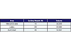
Table 1
The engineer’s analysis of a smoke control system for fire and life safety in an occupied structure focuses on two interconnected components. First, evaluating and understanding the dynamics of smoke production and controlling the smoke potentially generated by the building’s fuel packages; and second, determining the most effective way of removing smoke quickly from the building before occupant safety is compromised.
Occupied structures should be protected with automatic wet-pipe sprinkler systems equipped with quick response sprinklers (QRS). Before developing a sprinkler design though, the design engineer should prepare a preliminary smoke control design. We will review this design later as part of evaluating whether the smoke control system functions efficiently. Ultimately, the engineer’s analysis will propose a zoned smoke control system that meets criteria in chapter nine of the International Building Code (IBC) and/or NFPA 92A. The building’s floors will use proven smoke control technology prescribed in the referenced performance-based building code and design guide.
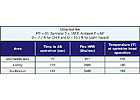
Table 2
Background
Many building projects will have mixed use occupancies that typically include space for “A” – assembly (dining areas or auditoriums); “B” – business (meeting rooms and offices); “M” – mercantile (retail sales); and “S” – storage, garages, and support. Such a situation can challenge the engineer developing a zoned smoke control system. However, despite this mixed-use configuration, there are design methods for achieving project fire and life safety goals.Building smoke control systems are designed to protect and maintain safe emergency egress space through and from a building. Additionally, the system inhibits smoke movement within the building and exhausts it outside as directly and quickly as possible.
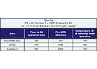
Table 3
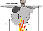
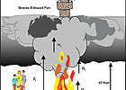
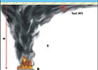
FIGURE 2. Fire profile with sprinklers activated.
The International Building Code Approach
Chapter nine outlines IBC smoke exhaust system design requirements. Three smoke control design options allow the designer differing approaches: pressurization, airflow, and exhaust.Pressurization uses physical smoke barriers to “keep the animal in the box” by preventing smoke from escaping the dedicated zone. Besides physical barriers, the zones’ atmospheres are controlled, based on fire alarm activation. Fire alarm activation initiates AHUs - either dedicated or non-dedicated - located outside and surrounding the zone of activation. The activated air handlers will direct 100% supply air into the non-fire zones. Pressurization prevents smoke from leaving its zone of origin and entering unaffected areas, resulting in a “sandwich” effect. One drawback of pressurization is that it does not require maintaining a suitable environment for occupancy. It isn’t even an objective. Pressurization’s only purpose is to contain smoke at its origin.
The airflow method is similar to pressurization, but provides air volume across permanent openings to prevent smoke from migrating through openings. The airflow method should not be used when the quantity or velocity of the air will affect the growth of the fire or the migration of the smoke. When air velocity meets or exceeds 200 fpm near the fire, it will adversely affect fire growth and smoke migration dynamics.
The exhaust methodis used to hold the smoke layer’s bottom at a height of six feet above the finished floor for 20 minutes. Twenty minutes is deemed adequate for occupant evacuation. Six feet is considered adequate because that is the statistical average height of individuals.
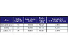
Table 4
The code characterizes a steady state fire as one of 5,000 Btuh/sec (5,275 kW in metric) unless a rational analysis could be provided without stringently limiting the amount of combustibles throughout the spaces. A steady state fire automatically provides energy output on ignition at time zero without any incubation, and grows to full size or decays after consuming the fuel package. This approach is conservative and is intended to cover various fire possibilities without engaging in extensive research, though the design may be “overkill.”
The rational analysis requires consideration of many factors – fuel, fuel load, effects of the initial fire and subsequent ignition of peripheral fuels, and if the fire’s growth will be steady or unsteady. The rational analysis uses minimum parameters. One would be the separation distances for secondary fuel packages. The minimum distance needs to be four times the radius of the initial fuel package for the secondary fuel package to be considered unscathed by the fire. Further, a minimum heat release rate per sq ft of mercantile space is estimated at 50 Btuh/sec, and that on activation of a sprinkler head, fire growth is inhibited, maintaining a steady heat release rate at the point of activation. This analytical criteria and approach is, generally, not fully understood by many architects or mechanical engineers.
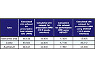
Table 5
Fire Protection Engineering Analysis
Many proposed on-floor mechanical smoke control systems are arranged as a series of zoned systems, configured to operate in the pressurization method. They supply fresh air to non-fire zones, and provide full exhaust in the fire zone. Based on the arrangement and location of smoke exhaust fans, the design intends to create a safe environment along the various occupant egress paths from the building.However, the pressurization configuration, which is not concerned with providing safe conditions for occupants, will not work in zones that are open to each other, such as lobby/circulation, mercantile, or dining areas. The airflow method is defeated when multiple doors are opened, diminishing the velocity and quantity of airflow across an opening. Thus, the IBC smoke exhaust method is believed more appropriate for providing both smoke control and an acceptable environment in these areas for occupants.
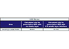
Table 6
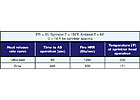
Table 7
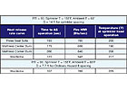
Table 8
This is based upon the inputs of:
Q = 5,000 Btuh/sec
Qc = 3,500 Btuh/sec
Zl (calculated flame height) = 13.9 ft
Equations used were:
mp= 0.022Qc1/3z5/3+0.0042Qcwhere the ceiling height was higher than z1(theflame height)
mp= 0.0208 Qc3/5zwhereceiling height was lower than z1.
All mass production was converted to volumetric production by using the equation:
| V= | 60 mp | Where = | 528 ro | |
| r | 460 + T |
and
ro= 0.075#/ft3and T = average temperatureof smoke plume
The second analysis method uses DETACT (DETectorACTivation), a computer model measuring sprinkler response times with given fire signature patterns. The rationale for using DETACT is based on the assumption that activated sprinklers will contain fire growth to a steady state of heat release.
Sprinkler head actuation assumes that discharged water cools the smoke plume to prevent its temperature from rising. Maximize spacing measurements to sprinkler heads in the computer program to the farthest permitted distance, based on “Light Hazard” and “Ordinary Hazard II” sprinkler spacing requirements for quick response sprinkler heads. This should yield a conservative calculation.
Heat release rates for these scenarios test the limits of industry-recognized burning characteristics. The heat release rates used were based on industry accepted “t-squared” fires to set the barometer.
Using the same parameters for DETACT as in the previously calculated steady state fire results in Table 2 and Table 3.
As demonstrated, the ultra-fast fire generates a greater heat release rate compared to a slow burning, smoldering fire. Using the same equations as in the prescriptive approach, but with information from the DETACT approach with the ultra-fast fire growth, and assuming that at sprinkler operation the HRR does not increase as the sprinkler heads control fire growth, the new calculations are shown in Table 4.
A comparison between the prescriptive and the performance based approaches, including the two different smoke layer heights, is shown in Table 5.

Table 9
All typical hazards present in given multi-story buildings areas should be analyzed. To gain a better understanding of the range of fires, DETACT was revisited using the ultra-fast and slow heat release rates. The parameters were changed with respect to the spacing of sprinkler heads, since spacing can be as much as 20 ft on center (400-sq-ft spacing) in some light hazard scenarios, and the height of the ceiling was dropped to 8 ft. The result is shown in Table 7.
Additional analysis located specific fuels in these areas. For example, burns were analyzed with a three-cushion sofa, a mattress in a corner, a mattress in the center, and a wardrobe furniture closet in light and ordinary settings. The wardrobe was tested with cloth material inside (Table 8).
The wardrobe arrangement in a light hazard area provides a worst-case scenario. The reason for the difference between the two wardrobe scenarios is the increased spacing requirements of an “Ordinary Hazard” classification, according to NFPA 13, which limits the maximum spacing to 130 sq ft/ sprinkler head as compared to the light hazard spacing of up to 400/sq ft.

Table 10
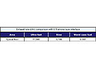
Table 11
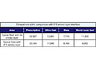
Table 12
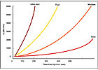
FIGURE 3. Heat release rates (HRR) for fire types.
When the heat release rates are imported into the axisymmetric equations, we find the results in Table 10.
If the smoke layer is contained at 6 ft above the floor, the exhaust rates are adjusted as shown in Table 11.
A summary of the prescriptive and performance-based scenarios is shown in Table 12.
In high-rise buildings, stairwells can be equipped with dedicated fans arranged to pressurize the enclosure on activation. Pressurization prevents smoke from entering the exit enclosure so occupants can leave the building safely, and allows fire fighters to assemble attack lines from the standpipe system. Fans should be placed at the top of each shaft.
Fans are sized to allow a minimum pressure differential of 0.15 in. w.c. at all openings, without requiring more than 15 lbs to unlatch the door, 30 lb to open the door and 15 lb to reach a fully open position.
The minimum pressure differential will be 0.15 in. of water and the maximum pressure difference shall be 0.35 in. w.c. to meet the 2006 IBC. Using a “Simple Stairway Pressurization” calculation from theASHRAE/SFPE Design of Smoke Management Systems, the required air volume to pressurize each stair is 4,341 cfm.
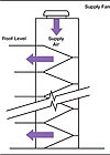
FIGURE 4. Pressurized stairwell.
Dedicated fans can also pressurize elevator shafts. On activating the fire alarm, elevator cars are captured at the dedicated discharge level, and fans activated to prevent smoke migration into the shafts.
Fan sizing is calculated similarly to stairwells, but using a lower w.c. pressure differential (.05 in. as prescribed by the 2006 IBC). Using the same parameters, except pressure, and a minimum 3 sq ft venting requirement for elevator shafts and a door leakage factor of 0.67 sq ft, the fan supply for each single car shaft is 4,291 cfm.
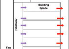
FIGURE 5. Pressurized elevator shaft.
Preliminary Discussions
The various smoke control zones need to be a direct reflection (same zone boundaries) of the sprinkler and fire alarm zones. Sprinkler/alarm activation should be from the affected zone. Manual pull stations should not actuate the smoke control system, although the fire alarm system will. Manual pull stations at exits should not activate the smoke control system because if someone notices a fire in a different zone and actuates the system from the zone they are in, but not where the fire actually is, exhaust fans could draw smoke and fire byproducts into the non-fire zone(s).The exhaust method only works if there is adequate makeup air. The source of makeup air will be determined as design of the mechanical system progresses. Makeup air can come from AHUs within the activation zone, from the automatic opening of egress doors, or from dedicated openings at a lower point of the floor that are enabled when smoke exhaust fans are activated.
Smoke control exhaust fans should be located in the zone they are exhausting to achieve the intended goal. If the exhaust fan cannot be located within its corresponding zone, ducted exhaust is an acceptable alternative.
Additionally, the ports drawing the smoke out of the areas should be at the highest point of the ceiling for that area. Smoke rises because of air density differences. Smoke will accumulate first at the highest point in the area before traveling under architectural trim to reach exhaust duct inlet ports.
Only axisymmetric fire plumes were calculated in these scenarios, based on currently available information. Different plume calculations may need to be evaluated. If doors and physical barriers are installed, a window plume calculation should be evaluated. Depending on ceiling arrangements, a balcony calculation may also need to be examined.
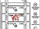
FIGURE 6. Building zone pressurization.


