PWM Drives The Standard
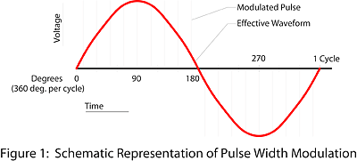
Nearly all vfd's used in hvacr systems today are of the pulse-width-modulated (PWM) type. These drives create a simulated sine wave output voltage of controlled frequency by rapidly switching to a dc voltage. The width of the dc pulses is varied to correspond to the magnitude of a sine wave of the desired frequency (sine-coded) and the smoothing effect of the motor inductance causes the resulting current to be nearly sinusoidal. See Figure 1.In early PWM drives the switching frequency was on the order of 2,000 cycles per second (Hz). Newer, high-speed switching devices called integrated gate bipolar transistors (IGBT), capable of switching high voltages and currents more rapidly, have permitted the switching frequency (also called the carrier frequency) to exceed 20 kHz. "High carrier frequency" vfd's have been popular in the hvac market because increasing the switching frequency pushes the frequency of motor noise generated by the vfd above the audible range. However, the use of IGBTs has created problems for the motor stemming from their fast turn-on and the resulting short rise time of the voltage pulse.
Not 'Motor Friendly'
Each ac motor winding consists of many turns of insulated wire. A normal sine wave voltage divides evenly among the turns resulting in low turn-to-turn voltage, permitting the use of very thin insulation on the individual wires and maximizing the amount of conductor cross section in the winding slots. However, this winding does not respond in the same manner to a voltage pulse. Pulses can be thought of as "traveling" down the conductor to the motor and as they reach the motor, the effect of the short rise time is to distribute the entire voltage of the pulse across the first few turns in the winding. This causes very high turn-to-turn voltages which can produce premature insulation breakdown.At this time, options for protecting the motor from the effects of IGBTs are somewhat limited. New "pulse-resistant" or "spike-resistant" winding insulation materials are available in some inverter-duty motors, but are not yet in use across the board in all motor types and areas of the market and there is not yet a large body of operating experience confirming their benefit. Line reactors or filters on the drive output or motor input can also be used, but add both cost and energy losses. When retrofitting an IGBT drive to an existing motor, they are definitely recommended.
Another effect of the high switching frequency is the possibility of creating "standing waves" on the motor circuit conductors if they exceed certain critical lengths. Standing waves are produced when the electrical characteristics of the conductor make it resonant at a frequency near the switching frequency. This results in a sustained over-voltage condition that can damage winding insulation and lead to failure.
To prevent standing waves, locate vfd's as close to the motor as practical (and don't forget that a local disconnect may be required ahead of the drive). Most vfd manufacturers specify maximum motor circuit lengths of between 50 and 150 ft, depending on the horsepower rating of the drive. Recent research indicates that, even in the absence of standing waves, the severity of voltage pulses at the motor is reduced by limiting lead length.


