Arcing Ground Faults
Most modern facilities in the United States are provided with three-phase electrical service at 480/277 V (See the September 1999 "Current Affairs" for a review of standard system voltages). While the higher voltage provides increased capacity over the 240/120 V and 208/120 V services that predominated in the past, there is an undesirable side effect. The combination of the higher voltage and the typical spacing between energized parts and grounded metal in distribution equipment create a condition in which arcing faults between a single phase conductor and ground can be sustained at relatively low levels of current, often below the normal load current in the circuit.In the early years of 480/277 V system use, a number of service burn-downs were attributed to sustained arcing ground faults which were not interrupted quickly because they involved current levels below normal load current and thus did not activate fuses or circuit breakers. These current levels, while low in comparison to faults involving two or more phases, are still high enough to dissipate substantial energy at the point of the fault, resulting in melting of metal, burning of insulation, and even explosive arcing. Detecting and quickly interrupting these low levels of ground fault current is the job of equipment-level Ground Fault Protection (GFP).
Principle Of Operation
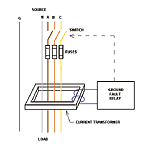
Equipment GFP functions on the same principle we discussed last month for GFCI protection; that of summing the currents flowing in all of the conductors of the circuit and considering any "missing" current to be a ground fault. Figure 1 illustrates a typical method of detecting a ground fault condition. A special type of sensing transformer, called a Current Transformer (CT), encloses the high-current power conductors in the switchboard or panelboard and produces a low-current output signal if all current flowing to the load does not return to the source through the phase or neutral conductors. The low current CT output is sensed by a ground fault relay, which has adjustable sensitivity and time delay settings. When a signal above the sensitivity setting, commonly called the pickup of the relay, persists for the length of the time delay setting, the relay operates to open the switch or circuit breaker.
Typical ground fault relays have pickup settings that are adjustable from 100 to 1,200 A and time delay-adjustable from instantaneous tripping to 0.5 seconds. The National Electrical Code (NEC) requires use of ground fault protection on low-voltage systems with solidly grounded neutrals rated 1,000 A or more when the voltage from any phase to ground is over 150 V. The NEC also dictates a maximum pickup setting of 1,200 A and a maximum delay of one second at 3,000 A.
Avoiding "Nuisance" Trips
The appropriate setting for ground fault relays should be determined by the electrical engineer as part of an overall protective device coordination study performed during design of the electrical system. Settings that are too sensitive or too fast may result in opening the switch or circuit breaker for ground faults in motors or other equipment before the branch circuit fuses or circuit breakers have a chance to open. If the settings are not sensitive enough, the relay may permit excessive damage to occur before interrupting the circuit.In many buildings, GFP is applied only at the main service disconnect because it is the only circuit rated over 1,000 A. This satisfies the NEC, but has the drawback that the building main must be tripped for a ground fault anywhere on the system. The low first cost of this approach may be more than offset by the cost of frequently interrupting power to the entire building. In critical facilities, where interruption of power presents either a high cost or a safety hazard, multiple levels of GFP should be provided throughout the system to minimize the extent of the outage when the GFP is required to operate. In fact, the NEC requires such multiple levels of GFP for health care facilities. ES
