


If motor-driven vapor compression chillers are much more energy efficient than absorption chillers, then why are we even having this conversation? In a hunt for LEED® points or in applications with certain demands, absorption could be just the ticket to sustainability and/or economy.
Does the idea of using steam, hot water, or direct-fired burners to generate chilled water sound like an oxymoron? Well, absorption chillers use these thermal energy sources to produce chilled water. Beyond the type of thermal energy source, absorption chillers are also classified by whether they are single- or double-effect. The goal of this article is to provide the reader with a basic description of absorption chillers and their advantages, specific applications, performance standards, and energy efficiency, plus how they can be used to gain LEED® certification points.
Water As A Refrigerant
How about using water as a refrigerant and lithium bromide as a salt to absorb the water? These are certainly not easily understood concepts. However, water has a very high specific heat and latent heat of vaporization, which makes it a great refrigerant.
How is water boiling at 212°F going to create chilled water at 44°? First, the boiling temperature of water is a direct function of pressure and at a pressure of 1 atmosphere (29.92 Hg), water boils at 212°. When the pressure on the water is decreased, the water boiling temperature is lowered. The following table gives the total pressure in inches of mercury and the corresponding approximate water boiling temperature at different pressures:
Absolute pressure Water boiling point (°F) 29.92 Hg (1 atm) 212° 2.99 Hg (0.1 atm) 115° 1.01 Hg 80° 0.30 Hg (0.01 atm) 45° 0.23 Hg 38°
Absorption chillers have substantially reduced internal pressures to take advantage of the lower water boiling temperatures. Absorption chiller internal pressures can range from 0.1 atmosphere (atm) to below 0.01 atm.
Absorption Chiller Description
There are a number of absorption chillers available, including single-effect indirect-fired (steam, hot water); double-effect indirect-fired; and double-effect direct-fired (gas and/or oil burner). Single-effect absorption chillers have a single generator/concentrator and condense all vaporized refrigerant in a single condenser. Double-effect absorption chillers have two generator/concentrators and the vaporized refrigerant from the high temperature generator/concentrator is the thermal source for the low temperature generator/concentrator, reducing the cooling requirement for the vaporized refrigerant.
Single-effect indirect-fired chillers are typically available in capacities between 100 and 1,350 tons with one manufacturer providing a unit up to 2,000 tons. Double-effect indirect-fired chillers are typically available in capacities between 100 and 1,500 tons, although one manufacturer provides a unit up to 5,000 tons. Double-effect direct-fired chillers are typically provided in capacities between 100 and 1,500 tons.

A description of the various single-effect, indirect-fired absorption chiller components is provided below followed by a description of the double-effect absorption chiller component that is different than the single-effect absorption chiller.
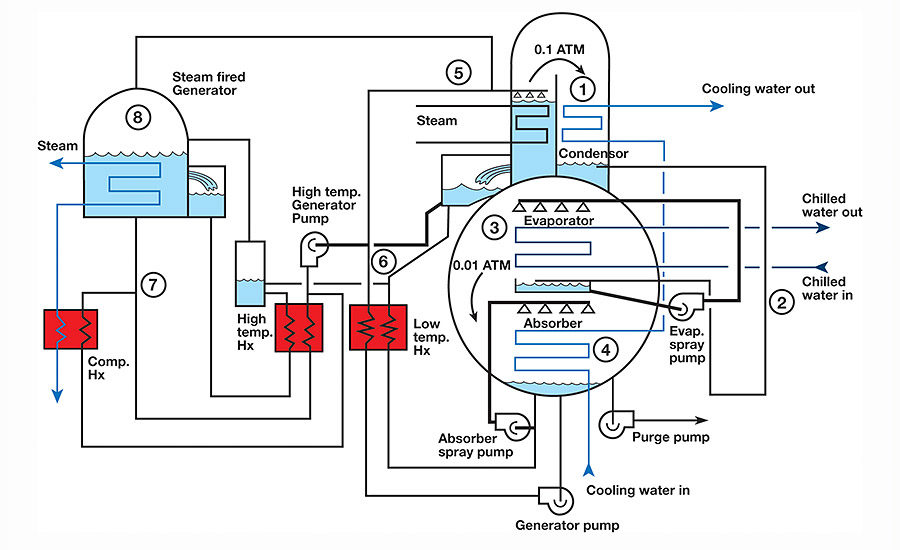
Single-effect absorption chiller. The single-effect indirect-fired absorption chiller has five main steps (Figure 1): condensing (condenser), expansion (expansion pipe), evaporation (evaporator), absorption (absorber), and generator/concentrator. See Figure A for schematic chiller diagram and Diagram 1 for the Duhring pressure/temperature diagram. Like the vapor compression chillers, absorption chillers have a high-pressure side (generator/concentrator, condenser) and low-pressure side (expansion pipe, evaporator, absorber). The following component descriptions will include some available options and standard operating parameters:
-
Condenser. In the condenser, the cooling water absorbs the heat of condensation from the vaporized refrigerant, changing the refrigerant into a liquid.
-
Expansion. The liquid refrigerant (water) travels from the condenser (0.1 atm) through expansion piping to the evaporator (less than 0.01 atm) during which the liquid refrigerant experiences a drop in pressure and temperature. The liquid refrigerant is discharged into a pan within the evaporator.
-
Evaporator. The liquid refrigerant (water) is pumped to the chilled water tube bundle top and sprayed on the tube bundle. At the low evaporator pressure (less than 0.01 atm), the liquid refrigerant vaporizes at approximately 38°, removing energy from the chilled water. Most lithium bromide absorption chillers can only produce chilled-water supply temperatures down to 40°. Liquid refrigerant that is not vaporized drops down to the pan and is recirculated. Liquid refrigerant that is vaporized travels from the evaporator to the absorber.
-
Absorber. The vaporized refrigerant enters a liquid lithium-bromide solution spray within the absorber. The lithium bromide solution absorbs the vaporized refrigerant and the cooling water absorbs the heat of vapor absorption. After the absorption, the liquid lithium-bromide solution takes one of two paths. One path has the liquid bromide solution mixing with a concentrated lithium bromide solution and being pumped to the absorber spray nozzles. The other path has the liquid bromide solution being heated and pumped to the generator/concentrator.
- Generator/concentrator. The lithium-bromide solution enters the generator/concentrator and is heated by steam or hot water, raising the lithium bromide solution to a temperature where the liquid refrigerant (water) vaporizes and travels to the condenser, completing the refrigerant cycle. The concentrated lithium bromide solution flows down to the absorber, completing the absorber cycle.
-
Double-effect absorption chiller. The double-effect chiller condensing (condenser), expansion (expansion pipe), evaporation (evaporator), and absorption (absorber) steps are the same as the single-effect chiller. The double-effect chiller has an additional generator/concentrator step that improves the overall efficiency of the chiller (Figure 2). The following is a description of the double-effect chiller generator/concentration.
- Generator/concentrator. The lithium-bromide solution enters the low-temperature generator/concentrator and is heated by the high temperature generator/concentrator vaporized refrigerant, raising the lithium-bromide solution to a temperature where the liquid refrigerant vaporizes and travels to the condenser. The high-temperature vaporized refrigerant discharges into the condenser.
The concentrated lithium bromide solution takes one of two paths. One path has the lithium-bromide solution flowing down to the absorber, being mixed with higher concentrated lithium-bromide solution coming from the high temperature generator/concentrator, heated, and discharged into absorber. The other path has the lithium-bromide solution being heated and pumped to the high temperature generator/concentrator where steam, hot water, or direct-fired heating is applied to raise the lithium bromide solution to a temperature where the liquid refrigerant vaporizes and travels to the condenser. The highly concentrated lithium bromide solution is mixed with the concentrated lithium bromide going to the absorber.

Chiller Performance Standard
The primary absorption chiller performance standard is ARI Standard 560 (2000 Standard for Absorption Water Chilling and Water Heating Packages). ARI Standard 560 applies to water cooled single-effect steam chillers, water cooled single-effect hot water chillers, water cooled double-effect steam chillers, water cooled double-effect hot water chillers, and water cooled double-effect direct-fired chillers. This standard provides testing standard conditions, rating requirements, minimum data requirements for published ratings, and integrated part load value (IPLV) or non-standard part load value (NPLV).
For performing the IPLV testing, ARI Standard 560 has established standard conditions for absorption chillers including:
- Entering condenser water temperature: 85°
- Condenser water flow rate: 3.6 gpm/ton (single-effect indirect fired)
- 4.0 gpm/ton (double-effect indirect fired, double-effect direct-fired)
- Condenser water-side fouling factor: 0.00025
- Evaporator leaving water temperature: 44°
- Evaporator water flow rate: 2.4 gpm/ton
- Evaporator waterside fouling factor: 0.0001
- Tube-side fouling factor (steam): 0.000 (indirect fired)
- Tube-side fouling factor (hot water): 0.0001 (indirect fired)
It is very important to understand that chillers rarely operate at their maximum capacity. ARI used typical building types and operations in 29 different cities to develop a chiller loading profile during a typical year. The resulting chiller loading profile is at 100% capacity about 1% of the time, 75% capacity about 42% of the time, 50% capacity about 45% of the time, and 25% capacity about 12% of the time. These values are incorporated into the IPLV equations, which are:
IPLV = 0.01A + 0.42B + 0.45C + 0.12D
(coefficient of performance [COP]) where:
A = COP at 100% capacity (condenser water at 85° )
B = COP at 75% capacity (condenser water at 77.5° )
C = COP at 50% capacity (condenser water at 70°)
D = COP at 25% capacity (condenser water at 70°)
IPLV = 1 (MBtuh/ton) where:
(0.01/A) + (0.42/B) + (0.45/C) + (0.12/D)
A = MBtuh/ton at 100% capacity (condenser water at 85° )
B = MBtuh/ton at 75% capacity (condenser water at 77.5°)
C = MBtuh/ton at 50% capacity (condenser water at 70°)
D = MBtuh/ton at 25% capacity (condenser water at 70°)

When evaluating different chiller energy usage, the IPLV provides the most accurate average chiller energy usage. When the known parameters are different than prescribed above, the part-load performance becomes NPLV which has the same equation as the IPLV. Ultimately, the chiller’s energy usage is primarily based upon the “lift” or temperature difference between the chilled water leaving temperature and condenser water leaving temperature. Lowering the condenser water leaving temperature or raising the chilled water leaving temperature will reduce lift and energy usage of chiller, but not necessarily chilled water system. Raising the condenser water leaving temperature or lowering the chilled water leaving temperature will increase lift and energy usage of chiller.
Chiller Operating Performance
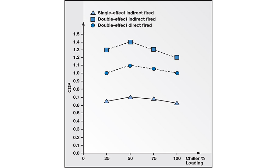
As with motor-driven vapor compression chillers, absorption chillers do not operate at the standard operating conditions noted above. Though there are many variables that can be evaluated; for this article, absorption chiller COP vs. part -load percentage and chilled water leaving temperature vs. chiller capacity shall be evaluated. Note that the graphs are illustrative only. It is important that you use the particular chiller performance data for the equipment you are evaluating.
Effect of part-load operation on chiller efficiency. Looking at Graph 1, all three types of absorption chillers are most efficient at 50% part load with the single-effect indirect-fired chiller having a 9.4% increase in efficiency; the double-effect direct-fired chiller having a 10% increase in efficiency; and the double-effect indirect-fired chiller having a 16.7% increase in efficiency. At part loads below 50%, the chiller efficiencies are lower as the chiller part load is lower.
Effect of chilled water leaving temperature. The standard chilled water leaving temperature is 44°. Looking at Graph 2, chiller capacity increases as the chilled water leaving temperature increases. At a chilled water leaving temperature of 48°, the chiller capacity increased 8% for single-effect absorption chiller and increased 9.5% for double-effect absorption chiller as compared to chilled water leaving temperature of 44°.
Conversely, the chiller capacity decreases as the chilled water leaving temperature decreases. At a chilled water leaving temperature of 40°, the chiller capacity decreased 14.5% for single-effect chiller and decreased 11.4% for double-effect absorption chiller as compared to chilled water leaving temperature of 44°.
Aborption Chillers And LEED®
The USGBC LEED for New Construction, Version 2.2, has a mandatory prerequisite to reduce ozone depletion by utilizing no CFC refrigerants in new construction and phasing out CFC refrigerants during renovation of existing facilities. Since the two frequently used absorption chiller refrigerants are ammonia and water, absorption chillers meet the Energy & Atmosphere Prerequisite 3, Fundamental Refrigerant Management, requirement of no CFC refrigerants.
The USGBC also provides the opportunity for obtaining a credit for Enhanced Refrigerant Management. Understanding some lower ozone-depleting refrigerants are also less efficient, the Energy & Atmosphere Credit 4, Enhanced Refrigerant Management has developed a formula that weighs a refrigerant’s ozone depletion and global warming potentials. If the project’s total installed refrigerant has an average atmospheric impact less than a 100, it is eligible for the credit (See USGBC for further information on formula).
The credit also recognizes “natural refrigerants” like water, carbon dioxide, ammonia, and propane as having a lower atmospheric damage potential and will allow projects exclusively using natural refrigerants to claim the credit without using the Enhanced Refrigerant Management formula. Absorption chillers can be a key component in meeting the USGBC strategy of reducing atmospheric damage.
Absorption Chiller Energy Efficiency
Absorption chiller energy efficiency is based upon fuel consumption per ton cooling while motor driven vapor compression chiller energy efficiency is based upon kW/ton cooling. The COP is a method for determining overall chiller energy performance.
For absorption chillers, the COP formula is:
COP = Eu / Ea
where: Eu = useful energy obtained (Btuh)
Ea = energy used (Btuh)
For motor-driven chillers, the COP formula is:
COP = 12
KW/ton x 3.412
Per manufacturer supplied information, the coefficient of performance range for the different absorption chiller types are as follows:
Absorption chiller type COP range
Hot water or steam
single-effect chiller..............0.60 to 0.75
Hot water or steam
double-effect chiller.............1.19 to 1.35
Direct fired double-effect
chiller.......................................1.07 to 1.18
Looking at the COP ranges, the single-effect chiller is the least energy-efficient absorption chiller type with the hot water, steam, and direct-fired, double-effect absorption chillers being almost twice as energy efficient. The hot water and steam double-effect absorption chillers are the most energy efficient absorption chillers, but how do they compare to motor driven vapor compression chillers?
The two motor-driven vapor compression chillers being utilized for energy efficiency comparison are the water cooled rotary screw chiller and the water cooled centrifugal chiller. Per manufacturer supplied information, the water cooled rotary screw chiller has a COP range of 3.90 to 5.40 while the water cooled centrifugal chiller has a COP range of 7.00 to 8.79. The result is that motor driven vapor compression chillers are 4 to 7 times more energy efficient than absorption chillers. This leads to a question: Why would you want to use an absorption chiller?
Advantages Of Using Absorption Chillers
In an energy-efficiency competition, motor-driven vapor compression chillers will beat absorption chillers every time. However, there are specific applications where absorption chillers have a substantial advantage over motor-driven vapor compression chillers. Some of those applications include:
- For a facility that has a cogeneration power plant or other thermal energy generating process with excess thermal energy, absorption chillers can utilize this excess thermal energy to produce chilled water instead of all the excess thermal energy being wasted.
- For a facility that has inadequate electrical infrastructure or bringing electrical infrastructure to the facility is cost prohibitive, absorption chillers have a substantially lower electrical power requirement than motor driven vapor compression chillers.
- For a facility with high electrical power cost and low fuel cost, absorption chillers may have a lower operating cost than motor driven vapor compression chillers.
- For a facility that requires substantial system reliability, the lower electrical requirements for absorption chillers will reduce emergency generator load requirements.
- For a facility that has high electrical demand charges, absorption chillers can be used as part of a peak shaving strategy.
- For a facility that has very low acoustical and/or vibration requirements, absorption chillers have lower noise and vibration generation than motor driven vapor compression chillers.
- For a facility wanting to use a “natural refrigerant,” absorption chillers are a good choice.
Summary
The future for absorption chillers is bright. With power utilities increasing electrical demand charges during peak hours as a strategy to delay building new power generating stations, absorption chillers can be the corner stone for an electrical demand limit strategy. With absorption chillers using “natural refrigerants,” they will become more attractive as more restrictions are placed on HCFC and other refrigerants. With the improved lithium bromide solution concentration control, absorption chillers are more reliable. ES

