


By Dan Reider
Our firm, Buford Goff and Associates, was selected for a chiller plant upgrade for the South Carolina Department of Mental Health in Columbia, SC. Initially, the project seemed to be a straightforward chiller/pump replacement. The existing chiller plant included a 1,200-ton and a 750-ton centrifugal water cooled chiller, a 1,200-ton and a 750-ton cooling tower, and associated pumps and accessories. The cooling towers were relatively new, but the chillers and chiller pumps were more than 30 years old.
Initial study: a Puzzle of a plant layout
The chiller plant serves two campuses for the Department of Mental Health (see campus plan). The Morris Village campus includes 18 buildings and the Bryan Psychiatric Hospital campus includes 22 buildings. The campuses house patients seeking help for drug and alcohol addiction. Most of the buildings are occupied 24 hrs/day but some of the administrative, support, and treatment buildings are occupied only during normal working hours Monday through Friday.
The existing chilled water system was a traditional primary/secondary pumping system. The primary pumps were located in the chiller plant and the secondary pumps were located in a pump room at each campus. Each campus pumping system utilized a mixing valve to control the volume of primary chilled water flow to each campus. These valves had not worked properly in many years resulting in sometimes higher water temperatures than acceptable and sometimes lower water temperatures than needed being pumped to each campus at various times throughout the year.
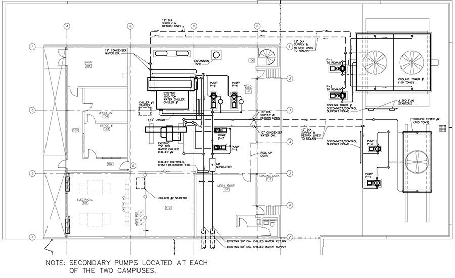
On many projects where we see unusual conditions, we can typically come up with a reasonable explanation or at least a good guess on why the original architects or engineers designed a system or building in a certain manner. After reviewing this chiller plant design, we were at a loss as to why the chiller plant would have been designed as it was. The chiller plant included two large chillers and four large chiller pumps (primary and back-up pump for each chiller) with a single roll-up door for getting large equipment in and out of the chiller plant. However, the chillers were installed to the interior of the chiller plant and the pumps and associate piping were installed towards the exterior.
To get the more accessible chiller in or out of the building, at least two pumps and associated piping would have to be removed. To remove the second chiller, all the pumps would have to be removed along with much of the piping, or two pumps would have to be removed along with one side of the building (see original chiller floor plan). Due to valve locations in the piping, any chiller removal would require shutdown of the entire plant. The equipment and valve placement increased the complexity of the replacement design considerably. In addition, the building has a high exposed roof structure with a lower piping support structure at approximately 14 ft, 8 in above the finished floor. Most of the piping structure was installed over the existing pumps (where the new chillers were to be installed), and only a minimal amount of pipe support structure was installed over the existing chillers (where the new pumping/piping systems were to be installed). A pair of secondary pumps were located in a mechanical room on each campus.
The second major issue found during the initial project study was that over the last five years, most of the 40 buildings on both campuses had their air handlers replaced. The previous air handlers had been replaced with new air handlers with new three-way control valves in lieu of two-way control valves.
Another major issue which had an impact on the phasing of construction was that the original condenser water design had the 1,200-ton tower operate with the 1,200-ton chiller and the 750-ton tower operate with the 750-ton chiller (i.e. no common condenser water loop). At some point, the owner added a crossover to allow either chiller to operate with either tower. The crossover was piped in about the only way it could be easily piped at the time it was installed, but the piping configuration would require an additional two shutdowns during construction to allow either new chiller to operate with either existing tower.
One last major issue that impacted the design and project phasing was the discovery, at least from the engineers’ perspective, that the 1,200-ton chiller was a 4,160/3ph machine and the 750-ton chiller was a 480/3ph machine. Each chiller was fed by two different electrical services to the building. The electrical service for both campuses was owner-owned. The existing transformers were determined at a later date to be contaminated with PCB’s, making their removal and the electrical work that much more difficult.
Also, as could probably be anticipated, some of the piping had insulating materials that contained asbestos. At least the two 20-in supply and return headers which we proposed to reuse had not tested positive for asbestos.
Recommendations
After reviewing the original drawings for the chiller plant and each campus and performing our field investigations, the decision was made to continue to use the existing 1,200-ton cooling tower and tower pumps, replace the existing 750-ton cooling tower and pumps, and replace the existing chillers and the existing primary/secondary pumps. The system could continue to be configured as a primary/secondary system or reconfigured as a variable flow primary system. The primary/secondary system would require less work, less downtime, and could be installed at a lower overall cost then a variable flow primary system. After analyzing the lifecycle cost (LCC) of the primary/secondary system versus the variable flow primary system, the decision was made in favor of the variable flow primary system.
The new chiller sizes considered were three 600-ton water cooled chillers, two 1,200-ton water cooled chillers, or two 750-ton water cooled chillers with a 400-ton air cooled chiller. The system load, including future construction, was slightly less than 1,200 tons. The owner was not particularly interested in an air-cooled machine from a maintenance, reliability, and efficiency standpoint, and the chiller plant could only accommodate two chillers. Some consideration was given to adding a small addition to the chiller plant for the third 600-ton chiller, but the final decision was made to design two 1,200-ton chillers. Chiller design temperatures were selected at 42/58?F.
Since a variable flow primary system was selected and all existing chilled control valves were three-way, all valves which had been replaced in the past few years had to be replaced with new two-way valves. For this project, pressure independent control valves were selected.
Not the same old bidding process
In South Carolina there have been a relatively small number of chiller projects through 2013 where the chillers were publicly bid and selected on the basis of lifecycle cost. In all the cases that we are aware of, the colleges or state agencies had the chiller bid separate from the remainder of the project so that the chillers could be evaluated on the basis of life cycle cost and not solely low cost. On those projects, chillers were bid and either the colleges and agencies assigned that chiller to the contractor as part of the overall project where the chiller was paid for out of the contractor’s contract (which had included an allowance to cover the anticipated cost of the chiller) or the chiller was simply purchased by the college or agency and turned over to the contractor for installation.
On this project, the project manager for the South Carolina Department of Mental Health wanted to find a way to bid the chillers on a LCC basis while including the bidding of the chillers in the overall project bid. After looking at various ways to accomplish this, the Department of Mental Health’s project manager suggested a method that she thought would work, be fair to all parties, and allow the suppliers to bid a chiller based upon LCC and low cost at the same time. After reviewing the pros and cons of her suggestions and considering the possibility of complaints by the chiller suppliers and contractors before or after the bid, we developed the methodology that was ultimately used in bidding the project. Although perhaps not perfect, we felt the methodology for bidding the chillers was at least as fair as the criteria used by the various colleges and state agencies where chillers were bid separately.
In lieu of requiring the chiller manufacturers to submit a bid for the chillers where the chiller would be selected based upon the lowest LCC, we as the design engineers established a maximum LCC for the bidders in the bid documents. The chiller manufacturers could bid any efficiency chiller they wanted but had to have a LCC less than we established in the bid documents. We did not require this information to be presented at the bid opening. The contractor was required to provide this information with the shop drawing submittal similar to the way the contractor typically submits chiller efficiency, performance, etc. (Table 1).
We had several discussions about the fairness of this approach versus bidding chillers separately. The projects where the chillers were bid separately had a maximum chiller cost. Our bid required a maximum LCC, but since we already knew the approximate cost of the chiller used in the life cycle analysis, we really also knew the maximum cost of the chillers being bid. As to the fairness of the chillers being based upon a LCC calculated by the engineers prior to bidding, we would argue that there are many assumptions made by the engineers, whether the chillers are bid solely by least LCC or in the way we bid the chillers. What really matters is that a reasonable methodology be established for calculating the LCC. The number of hours of operation at each cooling load, the entering condenser water temperature, the rate of increase of energy costs, etc., all impact the overall cost of ownership of the chillers. We have seen some LCC requirements for calculating efficiencies at four, five, or more different condenser water temperatures with the numbers of operating hours varying widely from 10% load to 100% load. Some calculations included variable speed condenser water pump energy and some did not. Other calculations included modest electrical rate increases and some included much higher predicted electrical rates. Some minor changes impact LCC significantly. There is no one perfect formula for predicting 25 years of chiller plant cost.
The project bid with almost no questions from the chiller manufacturers and contractors, even though this was the first time the chiller manufacturers and contractors had seen this approach for selecting chillers. After bidding, there were no protests or questions about the fairness of the approach we had taken, and all chiller manufacturers seemed fine with bidding chillers based upon a pre-established maximum life cycle cost.
Unfortunately, the bids were higher than expected, and the 750-ton cooling tower could not be replaced as planned in this project.
Construction Phase
Most of the construction occurred between March and the end of July 2014, when daytime temperatures were regularly in the upper 80s to the mid-90s. Since the chiller plant served many buildings that housed hundreds of patients, minimizing downtime of the chiller plant was of utmost importance. To minimize downtime, many isolation valves were identified to be installed at times when the system could be taken off line, such as cool evenings (particularly in March and April). The existing system generally had isolation valves in the piping in which we needed the valves, but primarily due to the swapping of locations of the pumps and chillers in the energy plant, the valves were not in the correct locations in the piping. Isolation valves were required in the following.
- Condenser water lines to each tower
- Chilled water lines branching from the 20-in headers in the plant
- New 12-in lines branching from the header in the plant
- Supply and return piping in each campus’ pump rooms.
The first phase of the project involved installing isolation valves on the existing chilled water lines from the 20-in header. Before the work could be done, glue containing asbestos was discovered on the header insulation. The insulation and glue had to be removed before work on the header began. Once the asbestos was removed, the isolation valves were installed, allowing the 750-ton chiller to be isolated and removed. Structural steel for pipe supports was installed as well as the first primary pump and the first 1,200-ton chiller. This chiller was brought on line and operated with the 750-ton tower (which was the tower associated with the existing 750-ton chiller). According to the new chiller manufacturers, we could operate the new 1,200-ton chiller with the 750-ton tower up until approximately 87 degrees ambient. As temperatures got warmer than 87 degrees, we found that flooding the tower basin continuously with cooler domestic water was necessary to allow the chiller to operate at warmer ambient temperatures.
A new temporary condenser water crossover was then constructed to allow the new 1,200-ton chiller to operate on the existing 1,200-ton cooling tower. Shortly after the existing 1,200-ton tower was piped to operate with the new chiller, the tower manufacturer was called in to modify the tower nozzles and repair damage to the hot basin. This work has been preplanned by the owner, but the work was not completed before the installation of the new chillers. The new 1,200-ton chiller had to be switched back again to the 750-ton tower for a period of about a week. Again, the flooded cold basin allowed the chiller to stay on line. After the tower repairs were done, the chiller was again valved back to the 1,200-ton tower, where it remains from that time forward. The 750-ton tower is used as a backup tower until the funds are procured to replace it with a new 1,200-ton tower.
The next phase involved installing the remainder of the needed isolation valves. These shutdowns were selected for the coolest evenings predicted by the weather service. These isolation valves did not necessarily eliminate all future shutdowns, but they allowed us to minimize the time required for the future shutdowns. For example, valves were added to the pump rooms at each campus. These valves made it simple to cut out the secondary pumps and install the prefab “bypass” piping. As the temperatures were continuing to get warmer, downtime in June and July had to be as quick as possible since nighttime temperatures were typically above 70?F.
After the first new 1,200-ton chiller was in operation for approximately two weeks, everyone was comfortable with its operation, and the contractor proceeded in removing the existing 1,200-ton chiller. This allowed the contaminated transformers to be removed and the new piping support steel, chillers, and pumps to be installed. At the same time, the 3-way valves at the air handlers were being changed to 2-way PICV valves. Until the new primary pumps were under control, the air handler valves were kept in the open position which resulted in some overcooling in some buildings which was preferable to not enough cooling.
The project was successfully completed for several reasons despite numerous challenges. The documents clearly indicated how the phasing was to be accomplished, including temporary piping and additional isolation valves. The method by which the chillers were bid was unconventional but proved to work very well. We plan on using the LCC criteria on future projects where a separate chiller bid is not desired by the owner. Fortunately, the low bid contractor, WO Blackstone in Columbia, SC, on this project had extensive experience on large chiller plants where the equipment serves occupied facilities and must be phased. The project might not have gone near as smoothly with a less experienced contractor.
Lastly, and most importantly, we had an owner and project managers who were very knowledgeable with all aspects of this project, were hands-on throughout the project, and were extremely helpful in coordinating system downtimes. The project was completed without additional costs related to the mechanical systems, due to the documents showing specific phasing requirements and the required additional isolation valves, and also due to good communication between owner, contractor, and engineering teams.
Dan Reider is a senior engineer with Buford Goff and Associates, Columbia, SC. He has been with the firm since 1984. He has designed mechanical systems for a wide range of projects including performing art centers, detention facilities, educational facilities, and hospitals. Reider says his firm believes that the implantation of design technologies should be based upon true value engineering, material and equipment reliability, system maintainability, and life cycle cost.


