MONTH 3- The Energy Conservation Opportunity: Process Heating for an Industrial Building Application - Solution Implementation and Monitor, Measure, and Benchmarking
We are at Month 3 of this B2B energy retrocommissioning test series. Month 1 and 2 were devoted to data collection, data analysis, and solution planning; and we are now at the Solution Implementation Phase. Using the existing system ATC/FPT system flow diagram for this test, we have incorporated the following energy conservation measures (ECM) from the completed energy retrocommissioning solution plan (full report not included in this test):
ECM1 thru ECM 8 featured in B2B June.
ECM9-12 - Complete hydraulic model to determine actual operating conditions based on the TAB engineers data collection.
ECM10 - Replace all 3-way valves at process equipment.
ECM11 - Add occupied-unoccupied cycle to the process heating system from Memorial Day through Labor Day in occupied mode for 2 shifts, Monday through Saturday. The rest of the time, system shall operate in unoccupied mode.
ECM12 - Add occupied-unoccupied summer season to the process heating system in occupied mode for 1 shift, Monday through Friday. The rest of the time, system shall operate in unoccupied mode.
It is important to note that when considering pumping strategy based on hydraulic modeling results that some design engineers may suggest trimming the existing pump impeller. It is this writer’s opinion that when an impeller is trimmed, the design engineer must look at the location of the new design performance variable speed pump curve points and assess whether this is the optimum selection for pumping efficiency. Also needing to be addressed is the labor to remove, trim, and reinstall the pump impeller, as well as replacement of the existing less-efficient pump motor. Also consider whether the new, smaller motor shaft will align with the existing pump casing. The bottom line is that the cost to trim an impeller may ultimately be more costly than simply going out and buying a new pump and high-efficiency motor selected at an optimum pump curve performance based on the new Basis of Design.
With the energy conservation initiatives agreed upon above, the energy retrocommissioning team will implement these enhance-ments and all the controls linked together into a building automation system (BAS) computer located in the facility engineer’s office to manage this retrocommissioning heat pump system. In addition, it is essential to have a plan in place to monitor, measure, and benchmark the past utility bills/energy performance versus this retrocommissioned project. If flow measuring devices and other means to trend system performance are added in the energy retrocommissioning initiative, then this data needs to be routinely reviewed, too.
Leading up to the energy retrocommissioning test, the TAB engineer will have balanced both the primary and secondary heating water systems and documented the results in the revised TAB System Flow diagrams at the following operating conditions:
- Deadhead the pump to reconfirm the correct pump impeller
- Maximum design heating season water flows
- Maximum design summer season water flows
Each of these flow diagrams, along with the other standard TAB forms used, will be included in an ATC/FPT/TAB Operator Hand-book that will be put in a three-ring binder and placed in the facility manager’s office for quick reference in the future.
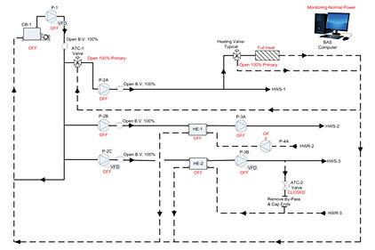
This month’s test requires you to refer to the new sequence of operation based on the energy conservation measures noted above and as shown in the ATC/FPT System Flow Diagram on page 2 of this B2B test. This new ATC sequence has been inputted into the functional performance test (FPT) retrocommissioning software, with the “reaction” device-by-device imbedded into the checklist below the flow diagram. It is your task to check off the “pass” activities as you verify this energy retrocommissioned system ATC/FPT. The answers can be found at www.esmagazine.com. The sequences selected are Sequence 1 Off-Fail Safe Condition, Sequence 2 On-Maximum Winter Heating, and Sequence 3 On-Maximum Summer Heating. For this system, there will be several other sequences of operation, as well as alarms and safeties to be commissioned (not part of this test).
The commissioning engineer’s ATC/FPT System Flow Diagrams and sequence-by-sequence of operation results shall be included in this Operator Handbook with the TAB Design-to-Actual results. Operating instructions will have occurred prior to the energy retrocommissioning implementation project and during the retrocommissioning of the entire heating system. Here again, the Operator Handbook being generated from this energy retrocommissioning initiative will include the new Basis of Design document to assure future reference data is available for any new operating personnel and to recommission this system.
The computerized maintenance management software (CMMS) system operator should update her asset database and preventive maintenance work order to assure this unit will receive the required care based on new system components. See the “Facility Files” column for a sample Preventive Maintenance Work Order for a process to pump.
As part of the project closeout, the team should also submit the necessary paperwork for third-party finance requirements, as well as any available utility company rebate(s) having received early approval of the utility rebate incentive in the Solution Plan Phase of this project.
At the project closeout meeting, the monitor, measure, and benchmarking assignment should be made and a monthly reporting system mutually agreed upon by the energy retrocommissioning team, so that there is a method to assess the work and also to look for new ways to improve the process heating system performance. The team should also have on their meeting agenda a lessons-learned discussion to make sure all documentation is completed, an electronic copy of the entire Energy Retrocommissioning Report is on file, system training is completed, and the PM work order system is current.


