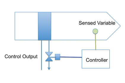
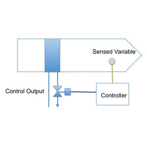
In any control loop we have a number of fundamental elements. The key elements are identified in figure 1:
|
|
Figure 1.The fundamental elements of a control loop. |
• Sensed variable: for example temperature, pressure, or humidity
• Controller: In this case, a DDC. Within the controller, we are executing a control loop, which may include proportional as well as integral and control strategies.
• Control output: The control output can be either binary (on / off) or analog. For now, we are going to focus on controlling an analog output (in this example a control valve).
Let’s focus on the details of how the control output is actuated. The controller is going to produce some form of analog signal that needs to be converted into a physical action, which will in turn position the control valve.
Signaling: The analog output from the controller is typically a 0 to 10 Volt DC or 4 to 20 mA. Other alternatives include digitally communicated values, or the use of set of binary outputs (one to drive open and the other closed).
Positioning and feedback: The challenge with controlling a mechanical device is that the positioning of the valve may not react smoothly and linearly with the control signal. Much of this is due to friction, flow, and hysteresis. As a result, changes in control output will not always result in a linear change to the output. The impacts of hysteresis will always exist but can be minimized by providing feedback on position within the controlled device. Without position feedback, control loops will tend to be more unstable.
Actuation: The actuator needs position the control output (in this case a valve) in responses to the output signal from the controller. The most common options for actuation include:
• Electronic actuators: These devices use small motors to position the valve stem. The electronic actuators typically have the ability to do positive positioning built into the actuator.
• Pneumatic actuators: These are often used for older systems that are retrofitted with DDC as well as on large valves and special applications for new installation. Pneumatic actuators require both a way to convert the signal from the controller into a pneumatic output, and they also typically require a pilot positioner to compensate for hysteresis.
A good control design and deployment will have accurate and stable control. While it is possible to do this with pneumatic actuation, it is more complicated and prone to error. This is why we prefer to see systems deployed with electronic actuation. ES
Paul and Ira first worked together on a series of ASHRAE projects including BACnet committee and “Guideline 13 – Specifying DDC Controls.” The formation of Building Intelligence Group provided them the ability to work together professionally providing assistance to owners with the planning, design, and development of Intelligent Building Systems.
Building Intelligence Group provides services for clients worldwide including leading universities, corporations, and developers. More information can be found at www.buildingintelligencegroup.com.


