
figure
1. An
example of an active chilled beam. (Photo courtesy of EHDD
Architecture.)
The wave of acceptance for this design option continues to grow in North America. Get up to speed on when and where chilled beams can have the most impact. Then move into humidity control, supply air, system sizing differences compared to VAV, economizers, and more.
The last ten years have seen a steady increase in the rate of adoption of chilled beams in the United States, as designers and facility owners have become more familiar with the many benefits of this energy-efficient technology. Already a standard design option in Europe, chilled beams are seeing their market in America rapidly approach maturity, with multiple domestic suppliers and a growing catalog of successful installations. Designing and installing active chilled beam systems is very similar to traditional systems, but there are a few key differences to consider in order to achieve the most effective and energy-efficient system. Careful attention to the design details discussed below can allow any engineer to add this efficient system type to his or her design toolbox.
OVERVIEW OF CHILLED BEAMS
There are two basic types of chilled beams: active and passive. Active chilled beams are a specific configuration of induction diffuser that requires connection to supply air and a hydronic loop or loops, while passive chilled beams are similar to hydronic heating radiators but configured as a ceiling panel with convective airflow providing cooling.
figure
2. A
rendering of an active beam system. (Image courtesy of EHDD
Architecture.)
A passive chilled beam relies on a room’s natural convection and has no direct air supply. Warm room air rises to the beam’s coil, which cools the air, causing it to fall into an occupied zone. A passive beam is best suited to cooling-only applications with low ventilation air requirements and low loads. While useful in many specific situations, passive chilled beams are less flexible and offer less capacity. This article will focus on the active chilled beam (referred to from this point on as simply chilled beams).
Chilled beams offer a simple design process with superior final efficiency. Designing with chilled beams is very similar to conventional system design. Chilled beams available in the U.S. generally have a 3:1 induction (room air to ventilation, or primary, air) ratio, are capable of 100 to 200 cfm of primary air per 6 ft of beam, and provide from 4,000 Btuh to 8,000 Btuh of sensible cooling per 6 ft of beam. Airflow, cooling, and sound performance vary considerably by manufacturer but are documented and readily available for design calculations in the same manner as performance data for a fancoil or split system unit. A key characteristic of chilled beam systems is that they use medium temperature chilled water at 55°F or higher, which can be produced more efficiently than the standard 44° chilled water used in many traditional hydronic cooling systems.
OUTSIDE AIR SUPPLY
By design, chilled beams should provide only sensible cooling (and heating, where required). A central air-handling system provides ventilation and latent cooling. In this way, cooling is “decoupled” from ventilation, specifically, an increase in cooling demand has no impact on the supply volume of air. The ventilation air handler is typically configured as a 100% outside air unit that does not recirculate air, referred to as a dedicated outside air system (DOAS). When used with chilled beams, a DOAS provides better air quality, ventilation monitoring, and quantity control than a VAV system while needing significantly less ducting and smaller, lower first cost air handlers. Decoupling the cooling load from the airflow rate is a major difference between, and advantage over, traditional VAV cooling systems, but it is not an unique design challenge that requires the discovery of new design methods. The same decoupling has traditionally been achieved through the use of fancoils and the same well-developed design approaches can be applied.HUMIDITY CONTROL
Since chilled beams are commonly supplied with medium temperature chilled water at 55° or higher, the “condensation problem” is no worse than the risk of condensation forming on the supply diffuser of a traditional all-air cooling system. With any mechanical cooling system, indoor humidity must be controlled and the chilled beam system is no exception. In a chilled beam system, the DOAS provides dehumidification in the form of dry ventilation air as required to control the space. The latent load of occupants can be served by dilution using the outside air provided for the purposes of ventilation. Where a ventilation rate higher than the code minimum is being used to meet client or other requests (such as LEED® rating system credit) the dewpoint of the supplied air can be increased and still maintain control of occupant latent loads, for example if the ventilation rate is 20 cfm per person, then 50° dewpoint dry air can be used.In order to harvest the energy benefit of higher chilled water temperatures in the chilled beams, a DX compressor can be used in the DOAS air handler to provide dehumidification subcooling. In most climate zones, over 80% of annual building cooling loads are sensible cooling loads not latent loads, so the lower efficiency of a DX system is offset by the efficiency benefits of a medium temperature chilled water system serving the vast majority of the load.
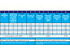
Table
1. A
bin analysis of three different systems.
The DOAS that are coupled with chilled beams are responsible for removing latent loads and maintaining a suitable building pressurization to keep untreated, humid air infiltration to a minimum. In most cases, outside air is the largest latent load and is easily removed: The DOAS dehumidifies the outside air before it enters the building. If additional latent loads from the space need treatment, ventilation air that is dryer than the target space humidity is delivered into the building. This approach works well for the latent load from people, where the latent load is proportional to the amount of outside ventilation air supply required.
SUPPLY AIR TEMPERATURE
Elimination of reheat is a major savings in a carefully designed chilled beam system. To realize this savings, it is critical that the supply air temperature be kept cooling-neutral, usually supplied in cooling at about 72° and heated to 55°, with additional cooling or heating supplied at the zone by the chilled beams. As discussed above, at the DOAS level a runaround loop between a precool and a reheat coil can be used in dehumidification climates to provide free reheat of the air after dehumidification while maintaining a neutral supply air temperature. A runaround loop of this configuration provides reheat with no need for boiler operation or other heat sources. In some cases, a wraparound heatpipe can perform the same function without requiring any pump.During the design process there is always an incentive to reduce the supply air temperature since doing so can reduce the cooling load in the zone and often the number of chilled beams required. In some cases, where all zones served have similar load profiles, a supply air temperature reset is a practical approach to reducing first cost, but the impact on reheat energy consumption in actual use must be carefully balanced. A reset based on outdoor air temperature down to 65° supply air temperature has been found to be reasonable in some cases where the DOAS was serving zones with similar shell load driving.
WATERSIDE ECONOMIZER
A critical component of a chilled beam system in many climates is a waterside economizer (or free cooling) system. A waterside economizer allows cool water to be produced directly from an evaporative cooling tower with no compressor energy required. This ability is the equivalent of a traditional airside economizer and integrates well with the medium-temperature chilled water a chilled beam system utilizes. Without an economizer system, in many climates the lower air volumes of a chilled beam system can put it at an energy disadvantage compared to a large traditional VAV system with airside economizer.AIR HANDLER AND DUCT SIZING
A key benefit of chilled beams is that they require less airflow, often a 60% size reduction compared to a traditional VAV system. This allows much smaller air handlers and ducting systems, but if standard VAV design practices are applied to a chilled beam system, which is basically a constant volume air system, a great deal of the potential fan savings can be lost. It is important to design a chilled beam system to have lower pressure drop than a VAV system.A traditional office VAV system very rarely operates at its full design fan power since shell and ventilation loads vary and are often never as high as the design condition. Depending on the climate, it is likely that in a VAV system the fan will be operating at significantly lower airflow rates than the ducts and air handler were designed for, reaping large pressure drop savings. But a chilled beam, with a much smaller investment in ducts and air handler, operates at or near its full design flow constantly, regardless of the load. Understanding this difference is critical in sizing the system to both minimize first cost and space while still saving energy.
To better understand how applying a standard air system design approach can lose fan savings in a chilled beam system, it is useful to look at a simple bin analysis of three systems (Table 1):
Case 1.A baseline VAV system where airflow is roughly proportional to the cooling load.
Case 2.A chilled beam system with a design airflow that is 60% lower than the baseline VAV system, with the ducting and air handler shrunk by a corresponding 60% reduction, but designed to the same pressure drop as in case 1.
Case 3. A chilled beam system where only a 50% downsizing of the air handler and ductwork was done, with the system designed to the lower airflow but also a lower pressure drop.
The first column shows the annual operating hours at the cooling load point shown in the second column for a sample building with a 2,600 hr operating year. The third column details the fan power used by a VAV system serving that load; note reduction in fan power as the VAV system turns down (this power is based upon the ASHRAE 90.1 Appendix G standard turndown curve). Meanwhile, the fan power in the case 2 and 3 chilled beam systems does not turn down as the load drops from 100% (design) to 50%, as seen in columns 5 and 7.
If a chilled beam system is sized like a miniature VAV system, much of the fan power savings is lost. In heating dominated climates, the chilled beam system may even show no savings. The constant volume nature of a chilled beam system increases the importance and potential of a low pressure drop design.
Significant fan power savings are easily achieved by designing the much lower volume chilled beam system for a lower W/cfm than a typical VAV system. Standard design rules of thumb are not appropriate. In particular, selecting air handlers for a 500 fpm face velocity, and designing duct systems to around 0.08 in w.g. of pressure drop per 100 ft of duct length, implicitly assumes a variable volume system that usually operates at flows below design flow. The balance of first cost vs. life cycle cost is different for a chilled beam system that is small but operating as a constant volume air system; air handler face velocities of 250 to 400 fpm and slightly upsized ducting are typically a better balance of first vs. operating cost and still much smaller and lower cost than a baseline VAV system.

figure
3. The
David and Lucile Packard Foundation office building uses chilled
beams to achieve a zero energy goal. (Photo courtesy of EHDD
Architecture.)
AIR VELOCITY AT OCCUPANT LEVEL
A final minor chilled beam design concern is drafts. Chilled beams can have a higher exit velocity than a standard diffuser. The higher air velocity is an integral part of how the induction process works. In most situations, the air velocity drops quickly and is not a concern at the occupied level, but in high density spaces beam placement may become close enough that airstreams collide and drop, causing drafts. This concern is no different than that presented by any diffuser in the same situation, but diffusers are smaller and easier to space out, so many designers neglect to check for this issue.INSTALLATION OVERVIEW
Installation of chilled beams presents few unique issues. They require hanging, controls and piping similar to fancoils or VAV boxes with reheat coils. Providing clear documentation and meeting with contractors to educate them prior to bid can help avoid bids driven up by contractor inexperience with chilled beams. Comparing the chilled beam with the installation time break down for fancoils, a familiar device, can be useful; the installation profile of the traditional fancoil is very similar to a chilled beam, with similar controls and piping requirements.The primary installation differences between a traditional fancoil and chilled beams are no electrical for the chilled beam, but the need to support a chilled beam from structure while also aligning it to a ceiling grid. With first generation products, alignment with the grid could take significant time, but the majority of chilled beam products now on the market provide slots or adjustable brackets at the mounting points to permit quicker and simpler alignment.


