Figure
1.
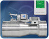
An example of an air valve and room temperature controller, both of
which are used in lab VAV systems. (Photo courtesy of Triatek.)
Terminal devices, pressurization, supply air, proper exhaust … those factors and more go into a well designed VAV system for sensitive lab applications. From general tips to changing details such as fabric duct elements, booster fans, and a new AMCA standard, the author equips you to succeed in one space that is no place for experimentation.
VAV systems have been used in laboratory exhaust and supply systems for years. This is mainly done for energy savings and not so much for comfort. Applying VAV to labs is an engineering challenge due to the need to maintain pressurization control in the lab spaces and the need to exhaust the air from the building in a safe manner, where the fume hood exhaust is forced away from the building and surrounding buildings so as not to be re-entrained into outside air intakes.
Figure
2.
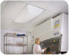
An example of fabric duct insulation used in a lab. (Photo courtesy
of DuctSox.)
A challenge of a VAV system in a lab is maintaining the proper pressurization of the lab space when the fume hoods and/or doors to the lab are opened and/or closed. These dynamic varying conditions can cause a lab space to swing from positive to negative or negative to positive if the VAV components in the supply and exhaust air ducts are not selected properly.
However, another challenge is to design the system economically and not arbitrarily fall into a trap of specifying products that are more expensive than needed to accomplish the functional requirements of a lab space. In addition, the benchmark has been raised in the fan industry with respect to economical fan applications that must take into account not only performance but also the required discharge plume, even when a lab building is in low utilization mode of operation.
Air distribution ceiling diffuser devices that can provide proper air velocities in the lab at low and high volumes without affecting the hood performance must be part of the HVAC system design consideration. Air supply and exhaust VAV devices must not only be responsive to the needs of the fume hood with respect to response time and accuracy but also with respect to material of construction compatible with the air passing through them. All of these criteria are achievable with VAV systems; however, there is a need to be aware of current products on the market to do it in a manner that balances functionality, maintainability, adaptability, energy use, and room pressure control, plus first-cost and operating cost objectives.
TYPES OF LABORATORIES
There are many types of laboratories in a variety of building types - animal research, pharmaceutical, industry research, academic, government, and private sector laboratories - to name a few. It’s generally worth looking at VAV in any type of laboratory facility in one way or another, either at a building level or on a local room level. This article won’t attempt to elaborate on VAV opportunities in each lab facility type. However, it is recommended the HVAC engineer be part of the design team early on in the design process for both new and retrofit laboratory projects to discuss VAV system opportunities before the architect, lab consultant, and lab users get too far into the design process.HOODS
We don’t get too deep into the various fume hood types in this article; there are plenty of other resources for understanding constant- and variable-volume hood types and functions. Even constant volume hoods that can be on/off in operation can be part of a building VAV system when these hoods are part of a manifolded VAV fan system. If the functional requirements can allow for VAV airflow, then indeed VAV airflow should be considered assuming the payback or life-cycle analysis of HVAC system and controls show this to be a good decision.VAV TERMINAL DEVICES
Determining which type of VAV terminal devices are appropriate involves several factors. It again depends on the functional requirement of the laboratory. In some laboratories, it is acceptable to use standard VAV boxes like in any commercial office space, except that the laboratory application will generally require either a fiber-free type of insulation or a double-wall VAV box with metal on the inside of the box. In some applications, a stainless steel VAV box may be required on the exhaust airstream for the hood but not for the general exhaust from the laboratory. Another option is to use a modulating concentric type damper with airflow measuring capability. These can be a good intermediate option between standard VAV boxes and air valves.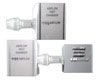
Figure
3.
AMCA has published a standard for testing fans. An example of AMCA
Standard 260 test setup #1 (top) and test setup #2 (bottom).
Part of the key to determining which product is truly needed is to understand the response time and accuracy of control that the VAV terminal devices need to adhere to in order to maintain the required pressurization in the space.
SUPPLY AIR
Supply air diffuser selections in a laboratory space are critical to ensure that the supply air does not disturb the performance of the hoods within the space. Depending on the air velocity requirements within the space and the quantity of air within the space, it may or may not be necessary to utilize some of the more expensive air diffusers on the market. Some labs may be able to get by with very inexpensive air devices; however, the engineer needs to clearly specify the material of construction and functional performance at both peak and part-load performance to ensure the air devices will perform appropriately over the entire range of airflow in a VAV system.This will require tighter specifications to clearly communicate that any or equal bidders understand that the “or equal” means equal in performance and not just in architectural appearance. This is true in any building application, and unfortunately, the air device industry has been taken to a low-cost commodity mentality focused on first cost and not performance. ASHRAE needs to focus more research time on air device performance testing in part-load conditions if codes are serious about enforcing ASHRAE Standards 55, 62, and 90.1. Manufacturers of air devices need to step up their game in documenting air device performance at low-flow conditions also in both cooling and heating modes.
Another exciting concept for air distribution within laboratories is the use of fabric air distribution diffusers. Fabric has been used for air distribution in laboratories in some cases, to deliver higher airflow volumes while lessening localized draft and noise that may deter proper performance by sensitive laboratory hoods or other equipment. Additionally, fabric air distribution diffusers can also can be effectively used in VAV systems and can be utilized in retrofit projects where the original specified metal air devices have did not provide the necessary performance, or when labs were renovated and greater airflow, less draft, or less noise was needed.
ROOM PRESSURIZATION TRANSFER AIR
Even in a VAV system, there is a need to have transfer air from a corridor or adjacent space into a laboratory. This transfer air needs to be controlled based on the pressure relationship, positive or negative, of the laboratory space to the adjacent space. The path of the transfer air can be via duct or door transfer grilles, depending on the sensitivity of the space with respect to noise, air filtration, and other factors. The amount of transfer air is dependent on the degree of positive or negative pressurization within the space. Depending on the use of the laboratory space, the transfer duct, if used, may need to be of special material or isolated in special ways.According to some sources, typical safety concerns are satisfied with a negative differential in the range of 0.01 to 0.02 in. w.g. A slight airflow can be noticed through an open doorway with a pressure differential of 0.01 in. w.g. The engineer should work with the architect to ensure the room construction and doors are as tight as possible to help minimize the amount of transfer air needed to maintain the required differential pressure in the lab space. When a door is open to a lab room that has no vestibule anti-room, then the speed of response of the general exhaust and supply air VAV terminal units may be more important, depending on the sensitivity of the lab space with respect to maintaining the pressurization differential.
EXHAUST AIR
In general, the exhaust air system capacity and air velocity must transport all hazardous airborne substances away from the origin and discharge them sufficiently high above the facility. These may include substances of one or more or a combination of chemical fumes, vapors, airborne biological substances, and various particulate and radioactive elements.Figure 1 indicates the use of a “high-plume” exhaust fan, as opposed to a physical stack. High-plume exhaust fans have grown in popularity, mainly due to the desire not to have tall physical stacks; however, the engineer needs to evaluate both for safety considerations when wind conditions are taken into account. There may be times when an air plume by a fan takes a considerable amount of energy and a physical stack is the better more economical choice for the project. This decision should be an engineering performance and not an architectural appearance decision, due to the liability on the engineer and owner of the facility.
Figure
4.
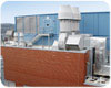
An example of an AMCA-certified induced draft high plume lab fan.
(Photo courtesy of Loren Cook.)
Laboratories typically use either dedicated or centralized exhaust system configurations. In a dedicated exhaust system, each fume hood has its own exhaust fan and ducts. In a centralized system, multiple fume hoods are connected to common manifolded exhaust ductwork. Either type can be VAV.
VAV FOR LABORATORY SPACES EXHAUST FANS
One of the most important decisions in a VAV lab application is the fan selection and control of those fans. There are many more choices on the market today than ever before. Engineers need not fall back on what was once considered acceptable, because newer proven technologies and products can often provide safer installations for their clients. More fan manufacturers have developed fans for various laboratory applications so that engineers have more choices.Although there is popularity in using induced draft, high-plume type fans, the engineer needs to realize that these are not needed in all applications. In many lab applications, such as high school chemistry labs, there is generally no need to use expensive high-plume induced draft fans; however, as with any engineering decision, the application needs to be analyzed.
One fairly recent piece of good news in the industry (and kudos to AMCA) is the new AMCA Standard 260-07 Laboratory Methods of Testing Induced Flow Fans for Rating, which gives credibility to tested performance data published by fan manufacturers. This provides a greater degree of assurance that the enduser gets what they are paying for and also provides a greater degree of liability protection for the engineer and the facility owner when dealing with contaminated exhaust airstreams. This standard was developed with input from all major fan manufacturers who are AMCA members.
The AMCA Standard 260 Setup #1 tests the fan inlet air capacity whereas the AMCA Standard 260 Setup #2 tests and quantifies the outlet capacity at the discharge of the windband, which includes the fan and induced air volumes. Without this new AMCA testing, previously there was no AMCA independent validation of the manufacturer’s marketing literature claims. Newer technology designs being validated by this AMCA test standard can ensure that the owner is indeed getting what he paid for and can add another level of liability protection for the engineer specifying these types of fans.
The key to specifying high-plume exhaust fans is to specify the outlet velocity of the wind band, not the nozzle velocity of the fan. Nozzle velocities can vary depending on the efficiency of the product design. A higher nozzle velocity does not necessarily result in the highest wind band velocity.
Engineers need to consider fan types, full and part-load performance, maintainability, dilution of exhaust air from the fans, energy recovery, redundancy, exhaust air discharge methods with stacks or high-plume exhaust streams, cross-wind velocity impact on the exhaust air from the stacks, or the impact of wind on the high plume of exhaust air. Engineers can use industry guidelines on analyzing the impact on the exhaust air due to winds around the building, or they can hire expert wind consulting companies to model their applications. With today’s increasingly stringent demands on indoor and environmental air quality, it may be worth the investment to hire experts in the field of wind tunnel modeling to share the liability of making the decision of fan types and discharge methods of laboratory exhaust streams.
STATE OF THE ART
Many people, professional organizations, code entities, and government research projects are continually looking at the safest ways to build laboratory facilities with the least amount of energy use, while ensuring safety for the users and the surrounding environment adjacent to the laboratory buildings. This includes looking at hoods, controls, air transport methods, and fans. One such example of this is the aforementioned AMCA Standard 260 to ensure that fan manufacturers of induced drafts fans do indeed perform as the marketing materials claim. Most of the major fan manufacturers are embracing this standard, which was a consensus standard by all of the AMCA fan members. There can be increased liability on the engineer and facility owner if non-AMCA certified fans are used when there are multiple AMCA certified fans on the market.There is one product that allows very low turndown of a VAV laboratory system’s main exhaust fan while not requiring this primary exhaust air fan to expend the energy needed to get the high plume desired above the building at high cross winds. A booster fan uses a separate power to develop the plume while allowing the building exhaust fan to turn-down to low levels. The booster fan allows the primary lab exhaust fan of significantly less horsepower since it no longer needs to be the main force provider for the plume.
MAINTENANCE AND OPERATION
Even the most sophisticated, energy-efficient laboratory HVAC VAV system can become ineffective if the system is not properly installed, maintained, and operated by the laboratory users. Education of the entire design and user team is essential to ensure that the energy savings projected in the design are realized in real applications. It is recommended that the O&M manuals of product equipment be reviewed early in a design process and also as part of the facility commissioning process before system types and product selections are made.Fans, filters, and ductwork maintenance are all part of the design considerations that should be taken into account to ensure laboratory exhaust systems are engineered correctly. Obviously, exhaust plume management is the primary objective. This starts with the hood sizing and selection, and then the filtration system needs to be considered. There are pros and cons to both direct and belt-drive fans including, accessibility and maintainability and access to the fan parts.

Figure
5.
An example of an inline high plume stack fan. (Photo courtesy of
Loren Cook.)
CODES AND STANDARDS
Various agencies and organizations have developed codes and standards affecting the design of research laboratories. These codes and standards are minimum requirements. Below is a listing of some codes and standards, but this is not an exhaustive list. It is always recommended to consult with the Authority Having Jurisdiction for governing codes. It is also recommended to consult with the building owner’s insurance agency to check what their insurance coverage requires. Many insurance agencies may require complete compliance with building codes, which include consideration of seismic bracing of the lab exhaust system and also suitable protection against wind forces on any rooftop exhaust fans.- AMCA Standard 260-07, “Laboratory Methods of Testing Induced
Flow Fans for Rating”
- ANSI/AIHA -
American National Standard Z9.5 for Laboratory Ventilation
- ANSI/ISEA Z358.1 - Emergency Eyewash and Shower Equipment
- Association for Assessment and
Accreditation of Laboratory Animal Care (AAALAC) standards
- Department of Health and Human Services, Centers for Disease
Control and Prevention and National Institutes of Health -
Biosafety in Microbiological and Biomedical Laboratories (BMBL) 5th
Edition. December 2009.
- Department of
Veterans Affairs Research Laboratory Design Guide
- General Services Administration (GSA): Facilities Standards for
the Public Buildings Service, P100
- National Institutes of Health (NIH): Design Policy and Guidelines
- National Institutes of Health (NIH):
Guidelines for the Laboratory Use of Chemical Carcinogens, Pub. No.
81-2385
- NFPA 30 - Flammable and
Combustible Liquids Code
- NFPA 45 - Fire
Protection for Laboratories using Chemical
- OSHA 29 CFR 1910.1450: OSHA-Occupational Exposures to Hazardous Chemicals in Laboratories ES