
figure
1. DOAMS
OA pre-conditioner flow schematic (patent pending).
MEP designers need to re-examine energy wasteful DOAS practices, which currently contribute to over-ventilation of occupied building space, and refocus on meaningful decoupling of sensible and latent load control using dynamic outside air management systems. Read more on the flexibility and possibility of the author’s proposed solution in data centers, schools, and elsewhere.
Dynamic outside air management systems (DOAMS) operates to maintain outside air (OA) dewpoint control, independent of whether the treated OA is delivered to AHUs providing sensible-only cooling; series or parallel fan-powered terminals; chilled beam units; or mini-split or conventional VAV AHU, and fancoil units.
As currently recommended in more recent ASHRAE Standard 90.1 findings, demand control ventilation (DCV) can significantly reduce energy wasteful over-ventilation using CO2sensor-based strategies, which can be expanded to extract additional energy savings in related air distribution heating and cooling systems applying DOAMS features. These features permit interaction with chiller internal controls to reduce refrigeration energy demands, provided that the DOAMS desiccant-assisted OA pre-conditioners deliver space-neutral drybulb temperatures in accordance with programmable thermostat setpoints located either in the conditioned space or common return air ductwork.
These features can be retrofitted within the majority of existing buildings without major modifications, or they can be provided initially as an integral feature of new building HVAC systems, as described below.
BENEFITS IN VARIOUS MICROCLIMATES
Refer to Figure 1 for an example of a DOAMS pre-conditioner designed to serve data center occupant and rack equipment needs when located in southeastern (and//or southern) U.S., coastal Puerto Rico, or Brazil, characterized by three representative microclimates ranging from moderate to high seasonal OA coincident design humidity and temperature.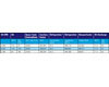
Table 1. Summary of energy usage (at
each of the conditions listed in Table 2).
Tables 1 and 2 summarize the estimated energy performance for the DOAMS pre-conditioner illustrated in Figure 1 when utilized in any of the three representative entering OA design conditions (as determined by computer simulation) operating to maintain indicated space drybulb temperatures and absolute humidity, including both process and regeneration energy use associated with delivering OA at the desired dewpoint to above referenced (sensible cooling-only) central A/C units.
Additional features are required to supply OA pre-conditioned air directly into the equipment space at a neural drybulb temperature (e.g., 70°), at the same dewpoint so as to prevent occupant discomfort and still meet ASHRAE TC 9.9 data center criteria for each of the earlier referenced Class 1, Class 2, and NEBS indoor environments.
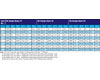
Table 2. Psychrometric conditions for
line numbers in Figure 1 for each OA design basis.
The solid desiccant (DH) wheel material coating has its own unique properties, which through appropriate manufacturer tests can be translated into a virtual performance map, relating specific operational features such as OA face velocity, mass flow rate, wheel speed, and wheel depth. The program logic controller (PLC) can then use the subject performance map to the best advantage in both dehumidifying and humidifying modalities, depending upon seasonal varying OA entering air drybulb and wetbulb temperatures, and depending on whether the flow rate is reset by the CO2 sensor demand ventilation controls operating through PLC as the interactive HVAC system “brain.”
Either of above referenced modalities are intended to be under the control of a PLC. In a cooling cycle, for example, the PLC will automatically adjust the DH wheel speed as needed to deliver the desired dewpoint, either directly to conditioned space, to a sensible-cooling-only recirculating AHU, a fanpowered VAV terminal, or chilled beam module.
A dewpoint controller (not shown), with sensor provided either at the DOAMS pre-conditioner unit discharge or located in a conditioned space, will be capable of adjusting the leaving DX2 coil discharge temperature via face and bypass (or equivalent temperature control means) through the PLC.
Based on sensor inputs, the PLC will adjust the self-contained variable-speed compressor to continue to operate to meet load requirements, via the OA flowrate sensor inputs, to avoid short-cycling and continued utilization of heat captured via desuperheating coil in both cooling and heating modalities. Pre-programmed PLC algorithms developed from tests performed by an affiliated manufacturer relate to the referenced performance data and enable energy-saving adjustments to proceed from full- to part-load operation.
Should humidification of OA air be required, simultaneous operation of the rotating DH wheel with higher rh air passing over DH wheel portion, shown in Figure 1, in the regeneration flow path exiting unit will transfer its moisture to entering OA. The OA, which has been preheated by the DX2 operating as a condenser (in heat pump heating mode) coil via compressor flow reversal, enables the dewpoint of the OA discharging from the speed-adjusted DH wheel to rise to a predetermined minimum at a temperature neutral drybulb temperature via additional heat supplied, if needed, via the DX1. The DX1 is also capable of operating as a condenser coil (in heat pump heating mode) prior to air being discharged directly to either the conditioned space; to a sensible, heating-only recirculating AHU; to a fan-powered VAV terminal; or to chilled beam module.
A list of applicable terminal unit types follows, provided they are deemed both suitable and cost-effective:
- Free-standing or above ceiling-mounted fancoil units with
split, remote condensing units discharging to ambient;
- Heat pump AHUs serving exterior building areas/zones in either heating or
cooling mode;
- Constant or variable all-air systems with or without series or parallel
fan-powered terminals;
- Multi-split ductless AHUs where primary OA would be supplied from DOAMS
pre-conditioners;
- Active chilled beam modules utilizing internal OA induction
devices;
- Passive chilled beam modules where primary OA would be supplied from DOAMS
pre-conditioners;
- Ceiling (cooling or heating panels) or embedded in- floor hydronic heating circuits
where primary OA would be supplied from DOAMS pre-conditioners;
- Freestanding, above, or mounted within finished ceiling induction terminals
where primary OA would be supplied from DOAMS
pre-conditioners;
- UFAD, deployed in combination with chilled beam modules in ceilings where primary OA would be supplied from DOAMS pre-conditioners.
As pointed out in the notes listed under Table 2, a net savings in DOAMS unit refrigeration compressor energy demand at design-day (cooling) conditions ranging from 5% to approximately 13% should result, depending upon which of the three OA microclimate conditions existed. Therefore, it is recommended that use of recirculated return and OA air mixtures be considered, particularly when a reduction in DOAMS compressor size, capacity, and/or cost may result.
Furthermore, it has been our experience that the ventilation efficiency for a 100% OA system is generally no lower than that for a multiple-zone system applied to the same building, provided the air distribution system has been properly designed and relief air used as indicated in Figure 1. Therefore, the complex situation requiring a burdensome multiple-zone computation, design, and control requirement can be eliminated in its entirety with initial new-building OA design or in a retrofit involving a DOAMS.
Information confirming why DOAS contributes to significant over-ventilation energy waste has been provided on the ES website referenced subsequently. The most important DOAMS feature extends the benefits of desiccant savings in refrigeration capacity to interconnected chiller energy savings to achieve a net estimated overall 40% energy savings demonstrated via a representative densely populated, intermittent (or variable) zone cooling space case study.
The results clearly challenge continuing wasteful use of ADP in coil selection and the benefits, particularly for the majority of existing building applications, of delivering CO2(or the ASHRAE approved DCV alternative) demand controlled ventilation air to modified sensible cooling-only AHU units, and automatically reset chiller higher chilled water temperatures. According to the ASHRAE Indoor Air Quality Guide, “DCV has the potential to reduce heating and cooling loads by as much as 20% or from $0.05/square foot (ft2) to more than $1/ft2annually.”
CONCLUSIONS
There is a need to re-examine energy wasteful DOAS practices, which contribute to approximately 20% over-ventilation of occupied building space, to refocus on meaningful de-coupling of sensible and latent load control, and to consider 100% OA when dealing with multiple-zone buildings served from common AHUs.DCV can significantly reduce wasteful over-ventilation by using state-of-art CO2controls and is being proposed for adoption by ASHRAE Standard 90.1 committee members in pending addenda. DOAMS features can be expanded to extract additional energy savings in related air-distribution and associated chiller cooling systems. Typically, one saves more energy in the chiller than one would expect to lose in the chilled and condenser water pumps, so one can still achieve the best energy efficiency by raising the chilled water temperature as much as possible under all cooling load conditions.
Having focused primarily on the energy efficiency of cooling, and having explored how to improve the operational cost of MEP facilities, we have found DOAMS pre-conditioners to be quite energy-efficient, reflecting energy savings of approximately 40% over conventional AHU designs and approximately 15% over DOAS constant OA (ventilation) delivery.
Resulting (cascaded) energy savings over the entire cooling season are likely to amortize the cost to install and operate a fully integrated DOAMS within one to three years following installation. Using return air, in combination with a desuperheating coil and sensible wheel as shown in the Figure 1 regeneration airflow configurations, permits a significant proportion of the energy required for regeneration of the DH wheel to be compressor waste heat, in addition to recovered waste heat via the downstream sensible wheel.
In all three microclimates evaluated earlier, a net cooling effect was achieved in Table 2, which substantially exceeded the installed refrigeration requirement. Use of desiccant and sensible wheels contributed to major energy savings, as compared to use of a standalone refrigeration unit operating between the same OA entering and leaving conditions.
Another advantage of resetting all the above referenced equipment in a controlled fashion via the PLC master controller is that one can also reduce the thermal time lag normally required to allow for both overshooting and undershooting the appropriate thermal load balance point: the so-called “hunting” typically seen when tracking actual load shifts, etc. This hunting can be substantially minimized by installation DOAMS feedback control loops, thereby resulting in further energy savings due to naturally occurring cloud cover effects on south-facing fenestration, for example.
The DOAMS pre-conditioner illustrated in Figure 1 also can accommodate free cooling when OA conditions permit. Or, it can operate as a heat pump in winter climates, enabling reversal of compressor refrigerant flow to capture available waste heat from the exhaust airstream (regeneration air) flow. This would both supply heat and humidify the OA during heating mode when serving data center administrative and other personnel areas as needed.
With higher-density equipment loads generating greater amounts of heat in data centers, especially following consolidation and virtualization of blade servers and communications equipment, having a clearly focused cooling strategy to deal with maintaining critical IT equipment operational efficiency is essential. For example, oversized cable openings in raised floors, along with unmanaged cutouts, can allow a significant amount of conditioned supply air to avoid passing through perforated floor tiles. Unused vertical spaces in racks can often result in unrestricted recycling of hot air rapid overheating.
A number of evaluation metrics are now being proposed by both industry and government experts to both measure and monitor the energy efficiency of data centers and other building types.
Typically, more energy is saved in the chiller than is lost in the chilled and condenser water pumps. To achieve the greatest energy efficiency, raise the chilled water temperature as much as possible under all cooling load conditions. The same argument can be made for VAV air distribution systems, since raising the chilled water temperature will result in an increased AHU air supply temperature, thus requiring the fans to operate at higher power. Typically, more energy is saved in the chiller than is lost in the fans, so here again, keeping the chilled water temperature highest at all load conditions still remains a good general rule of thumb.
Since the cooling load, and therefore occupant comfort, relates to the outside air drybulb and wetbulb temperatures, solar fenestration effects, and heat emitted by lights and equipment, the ability to react quickly to load changes becomes a major challenge that the proposed DOAMS can address in a more energy-efficient manner than separately controlled conventionally designed HVAC components have been able to achieve to date.
Meaningful consideration of ASHRAE’s policy statement on global warming in effect acknowledges that greenhouse gases are linked to global warming and must now be taken seriously by its members. Furthermore, Standard 62.1-2010 now addresses DCV in a newly added section. If one compares a DOAS (that ventilates at the design airflow during all occupied hours) with a DOAMS (which incorporates DCV), a significant amount of energy can be saved year-round, independent of local climatic conditions.
In summary, the recently updated ASHRAE Standard 62.1-2010 now defines DCV as “any means by which the breathing zone outdoor airflow (Vbz) can be varied to the occupied space or spaces on the actual or estimated number of occupants and/or ventilation requirements of the occupied zone.” Addendum G was also recently modified “to require documentation of assumptions, sequences. And set points of any DCV system,” such as DOAMS. The ultimate benefit of the above enhancements now requiring VAV systems to use “minimum expected primary airflow in the critical zone” will be to look to 100% OA systems and avoid the associated wasted energy consumption.ES
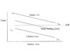
Figure 1
DOAM Systems Deliver Sustainable IAQ - Part 2
Design Build Systems welcomes the opportunity to explore some new opportunities and thinking when employing commercially available HVAC system components to achieve viable interactive energy saving results through use of proposed dynamic feedback control loops that build upon the best of both wired and wireless control protocols. The good news is that today’s commercially available BACnet® control features have improved energy performance capabilities creating new opportunities for expanding DOAMS pre-conditioner capabilities not currently available in commercially available standalone DOAS pre-conditioners.DOAMS is intended to increase current DOAS capabilities by operating under the control of a suitably configured programmable logic controller (PLC), utilizing algorithms provided by AHU and chiller manufacturers enabling applicable heat transfer formula, refrigeration compressor, chiller, and related cooling tower performance parameters to be simulated and reset as needed under varying and constant flow conditions. When these are integrated with low-cost EnOcean Alliance wireless battery-less, self-powered building sensors, thermostats, and controls (e.g. occupancy sensors, key-card switches, window position sensors, and other remote HVAC system controls (operating at 315 MHz in North America)) can work together and expand the range of overall HVAC energy savings.

Figure 2
INTEGRATION OF OA Ventilation with related HVAC SYSTEM OPERATIONS
A supervisory DOAMS control mode is critical for sustainable building ventilation and IAQ which serves to automatically establish the best method of operating each of the building occupied thermostatically controlled zones. The above referenced DOAMS PLC controller selects the most economic operating mode, (e.g. mechanical, free cooling and/or heating) and can also adjust the interconnected AHU control system setpoints based on the following independent variables:- Utility TOU or other applicable EPGS rate structure (electricity and gas) facility T&E load profiles
- Time-varying
electric load profile directly effecting:
- a. Equipment part-load performances (engine, chillers, cooling towers, pumps, etc.)
- b. Start-up and shutdown parameters and costs
- c. Maintenance planning (e.g., what equipment is available)
- d. Other O&M costs
Figure 3
Sequencing control of central cooling plants with multiple equipment options, (e.g., absorption and electric-drive chillers, or hybrid plants) serve to illustrate the dimensions of the control issues affecting actual real time energy use and cost.
Greater focus on the operating characteristics of chillers and related mechanical and electrical systems can also result in substantially improved predictions of “whole data center” annual energy cost. Chillers operate at design load for only a very short time, operating at less than rated capacity most of the year. Development of chiller-sequencing control algorithms based on manufacturer-provided polynomial equations can be employed to accurately predict the combined net effect of the following operative factors:
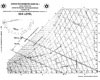
Figure 4
- The actual cooling load seen each hour for each sequenced set of operating chiller(s).
- The manufacturer’s rated kW/ton performance for electric chiller and, or the MBh/ton (thousand Btus per hour per ton of cooling) for absorption chillers at above part-load condition adjusted for all associated system fan and pump loads.
- The average condenser-water temperature (ECWT) entering the chiller(s) condenser(s) over any given operating period.
- Associated parasitic loads (pumps, fans, etc.) for all varying past load conditions as determined by performance interactive control strategies.
- Real-time monitored chilled and condenser return temperatures.
- Real-time monitored electrical cost ($/kWh).
- Real-time monitored natural gas (NG) cost ($/therm).
- Recognition that utility (EGSP) rate schedules, if updated hourly with actual corresponding ECWTs, permit central cooling and heating plant operators to achieve more cost effective and predictable control of chiller sequencing using forward simulation models capable of bringing together all of the monitored information listed above particularly if augmented by IT resources described earlier.
DATA CENTER OA VENTILATION CONTROL ISSUES
The advent of state-of-art remote data centers vs. customer purchase of desktop PCs, notebooks, and laptops including associated hardware, cabling, programming, and on-site redundancies required in the event of equipment failure, etc., is expected to challenge the latter IT modality as a continuing IT business model. Taking into account recent advances in virtualization, its effect on increasing power densities of rack mounted equipment, and resulting consequences for enabling energy conscious MEP designers and expansion of GHG emissions from serving, remote electric power generation systems (EPGS) demand immediate measures to constrain the environmental consequences of a growing, and consequential data center eco-footprint.Use of energy efficient DOAMS desiccant assisted pre-conditioners needed to maintain either Class 1, Class 2, and NEBS indoor air dewpoints when operated with modified existing (sensible-only cooling and distributed air conditioning and chiller systems), thereby eliminating need for CRAC integral unit humidity controls while achieving a estimated 60% to 80% (virtualized) reduction in the number servers, for example.
Freestanding computer room air conditioner (CRAC) units, have been found to fight each other in the same rack room and resulting when manufacturer provided humidity controls on some CRAC units call for dehumidification and other often adjacent while other CRAC units nearby are simultaneously calling for humidification, contributing to excessive data center energy use. This results from variations to be expected due to sensor sensitivity in overlapping dead bands separating.
As more attention is focused on data centers and the amount of energy it takes to power them, more companies are finding the commercial and public relations value in undertaking green IT projects. The problem is that there is very little standardization on how to measure green IT effectiveness when it comes to how green a data center actually is. The EPA's forthcoming Energy Star for data centers program may go a long way towards establishing this common standard, but the program is for U.S.-based data centers only.
News emerged recently of an international agreement to establish data center energy efficiency. The agreement is between The Green Grid (U.S.-based industry group), the U.S. Environmental Protection Agency, the European Commission Joint Research Centre, the Japan Ministry of Economy, Trade and Industry, and the Green IT Promotion Council (Japan-based industry group). For now the agreement is limited to these three regions, but could expand to include others such as China and India in the future.
The agreement establishes the power usage effectiveness (PUE) as the "preferred energy efficiency metric." Specifically, the agreement states the following shall be "guiding principles" as interim steps, and that data centers are "recommended" to measure PUE according to the principles:
- PUE is a measurement of the total energy of the data center divided by the IT energy consumption.
- The industry should improve IT measurement capability to enable take the measurement directly at the IT load (servers). At a minimum, IT energy measurements should be measured at the output of the UPS.
- For a dedicated data center, total energy measurement should include all energy sources at the point of utility handoff. For data centers in larger buildings, total energy should include all cooling, lighting, and support infrastructure in addition to IT load.

Figure 5
Additionally, further energy savings result since individual central air conditioners can have their discharge temperatures and interconnected chiller setpoints reset higher (since integral cooling coils will no longer be required to dehumidify supply air) only supplementary sensible load overhead or underfloor distribution needs thereby eliminating need for CRAC integral unit humidity controls.
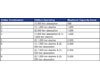
Table 1
DOAMS INTERACTION WITH BUILDING COOLING AND OA DEHUMIDIFIED AIR DISTRIBUTION SYSTEMS
By employing polynomial data available from the electric motor driven and natural gas-fired steam-driven absorption chiller manufacturers, one can more accurately determine part-load efficiency employing manufacturers generalized polynomial equations, applicable to both nominal 1,000-ton centrifugal, and nominal 500-ton, two-stage steam-fired absorption chillers referenced in Table 1.Cycling constant-speed condenser water pumps has been recommended by some practitioners, but certain minimum flows must be maintained to keep tower contact surfaces wet whether fans run or not. Otherwise, bypassing can occur and scale can build over time. Others report that throttling back on VFD tower fan drives to achieve a lower ECWT may offer greater power savings at the chiller compressor due to reduced refrigerant lift. Furthermore, parasitic loads are not necessarily constant over a wide range of part-load conditions.
Variable-speed tower fans provide the minimum power consumption when all cooling tower cells operate under all conditions except below manufacturer recommended minimum flow and above manufacturer prescribed minimum ECWT. Regardless of tower fan unloading, tower cells should remain operational since resulting tower pressure drops (at the spray nozzles) will automatically reduce parasitic condenser pumping energy use at part load.
The first step requires specification of a “real-time integrated” PLC programmed with the capability of establishing all of the foreseeable chiller operational combinations as load both ramps up and down during normal diurnal and design-day operating periods.
To illustrate, let us assume a hypothetical data center requires four chillers operating in parallel: two 1,000-ton electric centrifugal chillers and two 500-ton steam-fired double-effect gas absorption chillers. In doing the permutations, eight potential operating combinations can be programmed in the order of ascending building load as shown in Table 1.
If one assumes that all of the above chillers are configured in parallel, all operating chillers will load equally to the same percentage of chiller load. For example, in combination No.3, with a load of 600 tons, each chiller would load to 60% or 300 tons on each absorption chiller.
Tower airflow is directly proportional to fan speed, and therefore, its related power consumption varies approximately with the cube of the fan speed. As plant load varies, however, experience suggests that when adding tower capacity the lowest speed fans should be the first of the parasitic loads to be increased and then maintained at the same speeds in all cells at any given time. While tower fan use affects overall energy cost, its effect on estimated hourly energy cost is not believed to significantly affect the outcomes of proposed multiple chiller combinations selected, and can more easily be accounted for in estimating associated parasitic effects. Part-load conditions employing the above-referenced proportional fan-speed energy use and other simplifying operating assumptions can also be used, assuming that the manufacturer’s minimum flow rates are always maintained.
Normally parasitic load-adjusted kW/ton performance is directly affected by the ECWT rising and falling, thereby creating a dependency. This effect is generally more pronounced with mechanically driven vapor-compression chillers than with comparable absorption chillers, which typically have a narrower ECWT permissible range. Therefore, when formulating cooling tower part-load control sequences, a similar adjustment to estimates of MBh/ton values should be made.
Primary pumping systems serving building loads directly also experience changes to chilled water flows and temperatures (assuming two-way control values at all AHUs), primarily as a result of variations in building load. Such variations also impact chiller kW/ton or MBH/ton values when operating to maintain a predetermined chilled-water supply temperature set point through activation of their respective chiller integral load/unload control sequences. Accordingly, primary chilled water flow and return temperature variations can make predicting kW/ton and MBh/ton rates more challenging than modeling decoupled primary/secondary chilled water distribution systems.
Design conditions at which most chillers are selected usually require engineers to allow for the maximum possible condenser water temperature (peak design day wetbulb temperature). As a result, one usually provides more capacity than needed for most real-time operating periods. Additionally, whenever the entering the ECWT falls below that allowable, and actual chiller loading typically will decrease, further lowering capacity requirements. MEP engineers must, however, keep in mind that optimum energy efficiency is achieved when the major HVAC system energy consumer, such as the compressor - for vapor compression cycle machines -operates at its least overall $/ton-hour cost. For comparable absorption chillers, this also requires the high and low temperature solution heat exchangers to operate at their highest log mean temperature differential (LMTD) at design load.
Parasitic electrical loads associated with all respective absorption and electric chiller pumps can be computed from drawings and then accounted for as a fixed electrical load in kW/ton to accrue when each chiller is operating. The electric and absorption chiller parasitic loads include its associated primary and secondary chilled water pumps and condenser water pumps. Absorption chiller parasitic loads also include the solution pumps and purge pump.
Based on the above, the hybrid, multiple-chiller plant PLC’s control algorithm can be programmed to determine the optimum chiller combinations on an hourly basis for any given load condition, thereby more accurately determining the real-time operating cost/ton-hour for each feasible chiller combination. The provided algorithm limits are to recognize when a given chiller combination is appropriate for loads below manufacturer recommendations or when loads exceed recommended chiller combination capacity limits. By importing selected critical real-time and related operating parameters, one can better utilize the latest PLC equipment-sequencing control system technology for optimizing both hybrid and same-energy source chillers in any given central plant configuration
TAKING ADVANTAGE OF VARIABLE OA DIVERSITY
Application of a ”variable (CO2monitored) demand controlled OA ventilation cycle “can serve to increase overall chiller energy savings employing the DOAMS PLC controller in the following manner, for example. Assuming a realistic (yet conservative) 0.7 actual occupant usage, at any one time, net of unoccupied conference rooms, assembly areas, and other areas not being fully occupied as occupants move around, as part of their normal activities particularly where current “hoteling” company practices allow more of their employees to work at home and come into their offices only when necessary.Let us now consider the potential beneficial effect of above referenced CO2monitored, thermostatically controlled temperature zone if located in an exterior walled area with 20% glazing facing south within our hypothetical office building. Assume further that our HVAC designer had already determined that the above referenced zone required 350 cfm OA based on his interpretation of latest ASHRAE Standard 62.1 ventilation rate procedure after first computing the zone design-day supply air rate to be 1,400 cfm at 55°F. The latter supply air temperature was based on a our HVAC designers computed 30,800 Btuh sensible load and a 13,599 latent load from which he then determined his sensible heat ratio to be 0.7.
That would define a supply air flow, assuming a constant supply air - variable supply air temperature ducted distribution system operating at a constant 25% OA pre-mixed condition, or 350 cfm of OA at all times, independent of part-load cooling conditions which would prevail certainly on a diurnal basis most of the annual cooling season except for free cooling periods, where applicable.
Since the required OA flow rate (cfm) at any time other than the design-day condition for the subject zone can be approximated as 0.7 x 350 or approximately 245 cfm OA programmed through our DOAMS PNC to OA flow rate controller the corresponding recirculated return airflow mixed air proportion would automatically increase the zone return air flow rate from 1,050 [1,400 – 245] or 1,155 cfm.
With the AHU programmed to track sensible cooling only, it’s leaving coil temperature can now be reset by our programmed PLC to deliver supply air at 57° (rather than preset design-day 55° and easily computed via following ratio:[1,050/1,155] x 20 Delta T = 18º Delta T from which [75º – 18º Delta T] = 57º supply air still able to maintain the thermostatically controlled 75° space temperature. Therefore the net energy saved by our automatically reset space temperature neutral pre-conditioner discharge air temperature equals at then prevailing OA enthalpy (h) computed as follows: [(350 -245) x 4.5 x Delta h] or 472.5. Delta h Btuh., where Delta h is determined by the leaving condition of supply air exiting the AHU chilled water coil or at 55° db/°F wb. The initially unknown wb value will depend upon the required apparatus dewpoint (ADP), the cooling coil serpentine geometry, the number of fins/in. and the number of rows, the entering chilled water temperature and the coil by pass factor.
Refer next to Figure 2 for a graphical method of relating to the discharge air temperature off cooling coil of a given surface area, ADP and entering and leaving chilled water temperatures. The upper sloping line represents supply air temperature gradient as it passes through the exterior metallic surface of cooling coil commencing at it’s entering wetbulb temperature (located at upper left end) and its leaving wetbulb temperature (located at lower right end) The lower sloping line represents supply chilled water temperature gradient as it enters the serpentine cooling coil (in a counterflow configuration) commencing at it’s leaving temperature (at upper left end) and its entering wetbulb temperature (located at lower right end).
The intermediate parallel sloping line represents the cooling coil metallic surface temperature gradient and the dashed horizontal line intersection with the latter intermediate parallel sloping corresponds to the ADP value on the vertical temperature ordinate line. Fortunately, there are a number of commercially available coil manufacturers rating charts and/or software programs available for any given coil geometry, the number of coil fins/per ft (or in.), the entering supply air entering and leaving wetbulb temperatures, and the chilled water temperature and chilled water temperature rise through coil to establish its bypass factor so that we are able to find the appropriate zone supply air temperature for a given 0.7 sensible heat ratio (Figure 3) and maintained zone dr bulb temperature.
Accordingly if one selects an eight-row coil with 80 fins/ft, and with 44º entering chilled water temperature (from chiller) and a 10º temperature rise through cooling coil with a chilled water flow rate of 11.7 gpm, one can obtain a 55º supply temperature from AHU as shown in Figure 4.
Referring next to Figure 5, a psychometric chart illustrating the enthalpy differential between the 25% OA mixture point and the earlier computed supply air ADP or 9.29 Btu/# DBA. Therefore the actual coil cooling load (assuming standard air conditions@ 0.075 #/cu.ft. density) is
- 1,400 x 4.5 x 9.29 = 58,500 Btuh
- 350 cfm x { 0.68 x [86 – 51] + 1.08 x [85 – 75]} = 12,110 Btuh of which:
- 350 x { 0.68 x [86 – 77] + 1.08 x [85 – 75]} = 5,922 Btuh (represents the combined mechanical refrigeration load component at DX1 and DX2)
- [6178/0.85 + 5922]} or 13190 Btuh
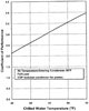
Figure 6
ADDITIONAL DOAMS CHILLER AND AIR DISTRIBUTION OPERATIONAL ENERGY SAVINGS
Most chilled water systems are still being conventionally designed to provide full cooling load with a chilled water supply temperature of 42º. Building operators typically leave the chilled water supply temperature fixed to avoid a sudden rise in space humidity levels. This is most inefficient since the zone air conditioning load can be expected to be well below its maximum or design-day cooling requirement most of the time. Typically, one would expect the chilled water temperature exiting the AHU by 5º to 10º much of the time. Practically speaking, even at full load, the typical over-sizing of airside components (AHUs, fancoils, etc.) usually could allow some increase in chilled water supply temperature, if not for HVAC designer humidity control concerns.Having now seen how the DOAMS pre-conditioner can be used to achieve additional AHU energy savings by eliminating the need to use its chilled water cooling coil to achieve a burdensome ADP operating temperature, lets now examine how that benefit can also be passed on through our PNC to the chiller’s motor driven compressor or the absorption cycles equivalent heat driven generator.
In our earlier AHU example we were able to provide the required zone net sensible cooling with 57º supply air as in the conventional AHU 55º supply air temperature example since we only require a 18º Delta T instead if a 20º Delta T across the AHU cooling coil for reasons given above. Therefore, while the PNC has actuated an automatic reset to the AHU cooling coil leaving air temperature from 55º to 57º thereby reducing the chiller load, it can also reset the supply chilled water temperature upward to account for that effect (Figure 6).
Keeping the chilled water supply temperature as high as possible at all times also results in an extended chain of cascading energy savings. An examination of chiller manufacturer technical literature or application of its available algorithms referenced earlier will show a net savings of approximately 2% of input energy to chiller per ºF that the leaving chilled water temperature is raised. Therefore, if we assume the chiller COP = 7.0, for example, based on a zone cooling load element of 58,500 Btuh design-day conditions, a 4% savings would amount to an additional 2,340 Btuh load reduction at chiller input energy providing an approximately 40% energy savings or 23,499 Btuh.

Figure 7
The same argument can be made for VAV air distribution systems, since raising the chilled water temperature will result in an increased AHU air supply temperature requiring the fans to operate at higher power. Typically, one still saves more energy in the chiller than one would expect to lose in the fans, so here
again keeping the chilled water temperature highest at all load conditions remains a good rule of thumb. Another advantage of resetting all the above referenced equipment in a controlled fashion via the PLC master controller, is that one can also reduce the thermal time lag needed to allow for both overshooting and undershooting the appropriate thermal balance - the so called “hunting” typically seen when tracking such actual load shifts etc. - which would minimized by installation of proposed DOAMS feedback control loops resulting in further energy savings, due to naturally occurring cloud cover effects on south facing fenestration, for example.
Examination of chiller manufacturer technical literature or application of its available algorithms referenced earlier will show a net savings of approximately 2% of input energy to chiller per ºF that results when the leaving chilled water temperature is raised. Therefore, if we assume the chiller COP = 7.0, for example, based on a design-day zone cooling load of 58,500 Btuh, a 4% savings would amount to an additional 2,340 Btuh load reduction at chiller input energy providing an approximately 40% energy savings (or 23,499 Btuh) in the DOAMS zone application illustrated above, for example.
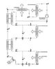
Figure 8
- A waterside economizer operating with operative weatherized cooling tower and interconnected plate and frame heat exchanger, or
- Maintaining a DOAMS preconditioner with process and regeneration fans only in operation but with DH and sensible wheels a inoperative
Figure 8 illustrates a temperature-entropy (T/E) diagram for a DOAMS OA heat pump operating in the cooling mode. Q2 represents the sensible and latent heat removed by OA coil DX2 and Q1 represents the sensible (only) load removed by DX1 to bring it to the desired space neutral d.b. temperature established by the PLC.
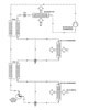
Figure 9
Figure 10 illustrates the refrigerant flow paths corresponding to the refrigerant state conditions, physical locations and respective air flows are identified by the same numbers “ 1” through “9” of individual heat components as shown in Figure 1 with the exception that all components shown in Figure 9 as evaporators are now identified as condensers, thereby rejecting heat to the respective air flow paths indicated. On a DOAMS preconditioner heat pump in heating mode, heat from exiting exhaust air via regeneration fan is reclaimed at desuperheater coil prior to its discharge to ambient (Figure 10) and is used to assist DH wheel then operating as a passive humidifier of entering OA.
Should it be desired to operate DOAMS pre-conditioners serving building interior areas only at a lower temperature than the space neutral for existing buildings for example, separate refrigerant expansion valves have been provided to operate DX2 and DX1 coils (Figure 9) at different suction temperatures so that DOAMS pre-conditioner discharge temperature could be lower than space neutral conditions providing additional sensible cooling capacity if needed.
Finally it should be understood that DOAMS preconditioner applications employing a CO2demand control ventilation (DCV) system was illustrated in Figure 1 for simplicity in single-zone system which are currently permitted.
Although multiple-zone systems, are not yet covered under later standard they have been thoroughly studied and reported on, most recently Standard 62.1 requires direct accounting for system ventilation efficiency when using multiple-zoned ventilation systems and multiple-zoned systems procedures outlined in ASHRAE Standard 62.1-2010 inherently over-ventilate all non-critical zones.
We believe DOAMS has a better answer by converting such systems to 100% OA for the following reason: DOAMS pre-conditioner applications shown above are capable of delivering space neutral temperature and constant de point air in both heating and cooling modalities. Furthermore as pointed out by author Dennis Stanke, who wrote, “In the example office building, the 100% outdoor air system may be more efficient than the multiple-zone systems.”
This should surprise no one who understands the level of energy currently being wasted in mixed OA and return air VAV systems as a result of DOAS requirements tied to the “critical zone methodology,” which could be eliminated by more energy efficient and improved EAQ in treated 100% outside air distribution systems operated in combination with passive natural ventilation opportunities when outdoor conditions permit use of operable windows, for example.ES


