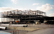
This engineer got very excited especially when it was decided to have him design a cooling system to limit the impact of motor heat gain on the building occupants and process equipment. The facility is the United Parcel Services Hub 2000 Project, located in Louisville, KY. This massive air hub facility houses conveyor systems that sort packages and encompasses over 45 acres under one roof. The final conveyor system build-out will contain approximately 33,000 motors, each with a vfd.
UPS had been planning this project for several years before our firm became involved in designing the building envelope. Many parameters had been worked out in advance, such as the general shape and size of the facility, including the stepped height of the roof. The building could not cast a "shadow" on the existing runways as seen from the air traffic control tower.
In other words, the building could not be in the tower's line of sight. Due to the location of the tower and the size and location of the proposed air hub, the building was to vary in height from approximately 80 ft to 25 ft depending on coordinates. Line-of-sight constraints would eventually dictate where roof-mounted hvac equipment could be placed.
The Conveyance of Cooling
During the planning stages of the building design, discussions took place as to whether the facility would employ mechanical cooling. Large summer ventilation fan systems, spot cooling, evaporative cooling schemes, and air conditioning were all considered.Some team members definitely wanted all or part of the new facility air conditioned due to first-hand experience with occupant dissatisfaction over summer temperatures on elevated mezzanines at other facilities. Other team members relied on experience with a large European facility that did not have problems with high indoor temperatures during the summer and felt that a properly designed ventilation system could suffice.
Elsewhere, there was a group of electrical engineers that was tabulating electrical load information. These engineers were heavily involved with the conveyor system design. When this group started sharing with the other team members what they were learning about the quantities of conveyor motors involved, things started to heat up.
It is important to note that there would eventually be five major conveyor vendors involved in competing to get a piece of the project before the electrical engineers could start designing their portion of the overall conveyor network. So hard numbers on the quantities, sizes, locations, and operating characteristics of these motors were not readily available to be considered in the initial planning stages of this project.
It was, however, quickly becoming apparent that the figures could be large and that the team needed answers fast.
Motor Heat
One obstacle that emerged was getting the team to agree on how the heat rejected from the conveyor system motors was to be calculated. At one meeting, it was announced that the team was not building an air hub, but instead a 1-MW oven.The group that was not inclined to have the facility cooled mechanically felt that the motor heat calculations might be overstated. Since the motors and the driven equipment would all be located inside the building, all work produced by these motors would eventually be liberated to the space in the form of heat.
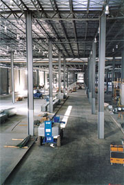
Additionally, the motors are not 100% efficient so that motor losses would also end up as heat rejected to the space. In the central core of the building, there would be three levels of conveyors stacked on intermediate steel with a fourth level of conveyors located on the mezzanine level. Motor heat trapped under the mezzanine slab could cause problems for the microprocessor-based conveyor control systems, not to mention the 165-degree F sprinkler heads.
Motor Losses
There are five categories of motor losses. Core or iron losses result from magnetizing the core material. These losses are constant for a given voltage and speed and include losses due to eddy currents that flow in the core. Core losses can represent up to 20% of the total motor losses.Windage and friction losses are also fixed losses and account for up to 10% of the total motor losses. These losses are due to bearing friction and air resistance around the motor components.
Stator losses are variable increasing with the load of the motor and can represent 40% of total motor losses. These losses are often called I2R losses, referring to the current flow (I) and the resistance (R) of the stator.
Rotor losses, like stator losses, appear as I2R losses and are variable, increasing with motor load. They account for approximately 20% of the total motor losses.
Stray load losses are generated by leakage flux induced by the motor current. They are variable losses and represent about 10% of the total motor losses.
In addition to the motor losses, the vfd's that will control the conveyor motors have losses associated with them. These are fairly fixed losses and can represent up to 2% of the entire motor output at full load. This is not a universally understood concept and can add up to a lot of Btu.
Consensus
After much discussion, it was finally agreed that all power consumed by the motors would eventually be rejected to the facility. Part of the team had believed that because work was being done by moving the packages on the conveyor, this component would not show up as heat to the space.A portion of the motor energy is liberated to the space at the motor itself, while a majority of it is transferred to the conveyor system and this work is eventually expended at the bearings.
The key figure in convincing all team members of this fact was Dr. Margaret Drake, formerly of Ohio State University. With a vivid thought experiment, she was able to get the team to visualize conveyor belts moving at extremely high velocities and ejecting packages from the facility at perhaps the escape velocity. The thought of packages orbiting the earth got everyone thinking on the correct path. She stated that this was the only way that a portion of the motor energy would not wind up as heat in the space.
Motor Load and Motor Use Factors
The heat gain to a space from a motor that has its driven load located in the same space is calculated by converting horsepower to Btuh and dividing by the motor efficiency. This results in the heat output at the full load of the motor.However, most motors are not fully loaded. In addition, they may not normally operate on a continuous basis. To get an accurate estimate of the heat gain to the space, the motor load and motor use or run time must be properly considered. For some projects this may be a simple task.
For the UPS Hub 2000 project, this was anything but simple. As mentioned previously, there was to be five major conveyor vendors involved, most of which had not fully begun their system design at this point.
In addition to motor load and use factors, the team was not sure how many motors there would be, what hp, or where they would be located. Assuming that both the motor load and motor use factor is 0.7, multiplying these together yields 0.49. This would then represent half of the full load motor gain under continuous operation.
This example illustrates how important these factors are in accurately calculating motor heat gain to a space. Members of the UPS electrical group took amperage readings at similar, but smaller facilities and came up with good motor load and use factor estimates. Once the motor load estimates were finally tabulated, hvac system concepts were then seriously discussed.
To Temper or Not To Temper
Once it was determined that large portions of the facility should be mechanically cooled, attention was then focused on what the summer interior design temperature should be.A typical air conditioning system would attempt to maintain an indoor temperature of 75 degrees. It was decided that certain portions of the facility would not be mechanically cooled. These are the "wings" of the building where motor loads would be less dense.
Because of this, it was then decided that it would not be appropriate to cool other portions of the facility down to 75 degrees. It was felt that it would be unfair to have employees working under different environmental conditions.
In addition, there are numerous overhead doors that are often left open in these areas, creating a scenario where the hvac systems would attempt to condition the outdoors.
Considering these factors, it was decided to design the cooling systems to maintain the indoor environment of the main building core at a maximum of 95 degrees during the summer.
This system would be labeled a tempered air system, as it would be designed to remove the motor heat from the space and not drive down the facility temperature below the outdoor temperature on a design day.
The tempered air systems would deliver air at 75 degrees on the hottest days of the year. This elevated air delivery temperature would also reduce occupant discomfort, as standing next to an industrial louvered grille delivering 4,200 cfm of 55 degree air could be distressing.
The only potential drawback to this concept is the possibility that under certain meteorological conditions, condensation could occur on interior building or system components. Such a scenario would involve a period of cold outdoor temperatures followed by a rapid rise in both the outdoor temperature and humidity.
Designing the system to perform latent cooling during the summer to avoid this type of event would have required perhaps 40% more cooling capacity to be installed. Due to cost, it was decided against designing for latent cooling capacity.
However, the AHUs were designed to accept additional cooling coils at a future date to accomplish this task. In addition, chilled water pipe sizes were increased, and space was set aside for additional cooling equipment.
Project of the Year
The hvac systems as finally designed were reported to be the largest air conditioning project in the world in 1999 and the hvac vendor, the Trane Company, selected it as project of the year at its annual sales meeting. The initial phase included a 9,600-ton cooling plant comprised of 24 400-ton air cooled chillers. The chillers were located on four separate roof-mounted platforms.Columns were stubbed up above the roof to accommodate three additional chiller platforms so that eventually up to 48 400-ton chillers could be installed. Each platform also has a packaged pumping system enclosed in a weatherproof housing to distribute the 20% ethylene glycol solution to roof-mounted AHUs that constitute the bulk of the tempered air system. At peak flow, the combined systems pump nearly 16,000 gpm through miles of piping. The piping system devoured approximately 60,000 gallons of premixed glycol solution.
The tempered air system delivers over 3 million cfm to the space through 31 custom rooftop AHUs and 16 custom, vertical indoor AHUs. Much of the air is delivered below a mezzanine level through massive 10- by 4.5-ft vertical ducts where it is distributed at double- walled acoustical plenums through louvered grilles. Another 30 AHUs serve nearly 200,000 sq ft of conditioned office and support space.
As mentioned before, portions of the facility are not served by the tempered air system. These areas were dubbed the wings and have a much lower motor density than the "core" of the facility, and are served by direct-fired pressurization units mounted on the roof. These units deliver 1.5 million cfm of 55-degree heated air during the winter and 100% outdoor air during the summer for ventilation. Over 80 strategically placed exhaust fans remove another 2.6 million cfm of hot air during the summer to keep temperatures down.
Special Sequences of Operation
Some unique sequences of operation were developed to handle the temperature control functions of the facility. One feature was the use of the massive structure itself as a thermal flywheel. Calculations were performed to estimate the amount of energy that would be stored or could be absorbed into the tons of steel and concrete that would exist in the space to be cooled.The hvac system is set up to automatically start before the day shift arrives to slowly drive the space temperature down by removing thermal energy from the structure. When the conveyor systems start and the building is occupied, the hvac system already has a head start on keeping the space cool.
Nearing the end of the shift, the space may reach its summer design temperature of 95 degrees. The precooling space temperature setpoint is reset depending upon the outside air conditions so that as the outdoor air temperature drops, the indoor space temperature is lowered also. The indoor dewpoint temperature is monitored and the space is prevented from being precooled less than 2 degrees above the dewpoint to ensure that no condensation will occur.
As mentioned previously, the initial phase of the cooling system is composed of four chilled water plants located outdoors on roof platforms. During cool and cold weather, most of the air-handling system can revert to an airside economizer cycle to cool without mechanical refrigeration.
However, there are air handlers that are buried deep in the core of the building and do not have access to outside air for an economizer cycle. These units are spread across the facility and are fed from all four chilled water loops. It would not be practical to run all four plants to accommodate the small chilled water load during these periods.
Therefore during the economizer mode, isolation valves are opened to interconnect all four chilled water loops to serve the units that cannot operate on outside air. At this time, three of the chilled water plants are locked out from operation and one plant is operated to carry this residual cooling load.
During warm weather, these isolation valves close again to form four independent loops and all four chilled water plants are then enabled.

