Figure
1.
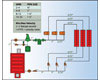
An example of a piping arrangement to avoid velocity noise.
(Illustration courtesy of Taco.)
In light commercial hydronic systems, design challenges may be solved by using a fixed Delta-T (DT), variable-speed circulator as the main pump. Or with larger, whole-building hydronic systems that heat and cool, a constant-circulation strategy that moves large volumes of Btu’s while permitting fancoil units to tap the “river’s flow” can save precious thermal energy. Fancoil design, pumping stations, and these contemporary updates on proven hydronic concepts can all contribute to your system efficiency.
The “green revolution” has forced professionals around the globe to reassess building systems large and small. As with our fascination with automobiles, hydronic industry pros too often fixate on the “engine.”
So it’s fitting that boiler manufacturers have greatly enhanced system efficiency within the box. Placing that machine within the context of large distribution system is the next step, and it’s one that either positively or negatively affects the efficiency of thermal energy transfer.
Without question, market forces - chiefly, the push for higher and higher energy efficiencies and demand for equipment to go where no equipment has easily gone before - are driving the pace for new and innovative hydronic solutions.
The newest generation of hydronic equipment - such as condensing technology that purposefully extracts heat from condensate within the system - has pushed combustion efficiency into the 95% to 99% range. Add a circulation strategy that either adjusts automatically to temperature differential or larger systems with constant flow that allow easy access to water volume for thermal transfer, and that’s smart use of energy.
How effectively a boiler or chiller relates to the total system is determined by its capacity to deliver or dispel heat efficiently. Piping and pumping are key factors in designing and building an efficient system. The most efficient boiler or chiller can’t make an entire system efficient if the system isn’t piped and pumped correctly.
And there’s response to outdoor temperatures, water storage temperatures, and system loop temperatures. These, too, are very important contributors to overall system performance.
SMALLER COMMERCIAL SYSTEMS
There’s been a lot of buzz these days about variable-speed circulation. A variable-speed circulator automatically adjusts its speed based on heating load demands or how many Btuh are needed in a structure. To understand how it does that, let’s take a quick look at the universal hydronics formula.
Figure
2.
A simplified reference to “river” flow in a large, constant
circulation system. (Illustration courtesy of IEC.)
Gpm = Btuh ÷ DT ÷ 500.
Let’s define the terms.
GPM: gallons per minute/flow rate needed to deliver the required Btuh.
Btuh:British thermal units or Btuh, or the required amount of heat for a building or zone at any given point in time (outdoor temps or the number of people within a building affect the Btuh load).
DT:is the designed temperature drop across the piping circuit. In a baseboard zone, the design DT is usually best at 20°, meaning the water might enter a baseboard zone at 180°F and return to the boiler at 160°. For many radiant floor heating systems the design DT is usually about 10° degrees.
This 10° DT is important because it ensures an even, comfortable floor surface temperature throughout a room. A wider DT would likely create greater variation in floor surface temperatures.
The final element of this equation is 500. That’s a shortcut that represents the weight of 1 gal of water (8.33 pounds) multiplied by 60 min in an hour, again multiplied by a specific heat characteristic of the fluid, which is “1” for 100% water (it takes one Btuh to raise the temperature of one pound of water 1° in 1 hr: 8.33 x 60 x 1 = 499.8).
At Cranston, RI-based Taco, John Barba, residential training/trade program manager, proposed a unique way of assessing the performance of a small commercial hydronic system.
“Let’s say we have a small restaurant with a heat loss of 75,000 Btuh with an outdoor design temp of 0°F,” said Barba. “The job calls for three zones of fintube baseboard; each zone has a 25,000 Btuh heating level. Each zone is designed to a 20° DT.”
“Remember that gpm equals Btuh divided by (DTx 500). In this case, gpm = 75,000 ÷ (20 x 500), or [75,000/(20 x 500)] = 10,000. So, 75,000 ÷ 10,000 gives us a flow rate for the job of 7.5 gpm.” He added. “Each zone has a heating load of 25,000 Btuh. If we plug this information into our formula, we would divide the load, 25,000, by 20 times 500, or 10,000, for a flow rate per zone of 2.5 gpm.”
Knowing this, we can now size the pipe. Using the following guidelines, the proper pipe size for the boiler supply and return pipe, the distribution header and the zone piping can be determined.
In Figure 1, pipe sizing guidelines are all based on minimum and maximum flow velocities and maximum head losses. Recommended design parameters are a minimum of 2 ft per second (fps) and a maximum of 4 fps at a maximum of 5 ft per 100 ft. of head loss. Head loss of 4 ft per 100 ft. will rule in smaller pipe, resulting in maximum velocities of four fps, above which flow velocity noise will occur. In larger pipe, velocity of 8 fps will rule, resulting in pressure drops below 4 ft per 100 ft. Larger pipe can withstand higher velocities without noise.
The piping arrangement is next. This hydronic recipe calls for 1-in. pipe and 7.5 gpm. At the header, it would be typical to branch off into 0.75-in. lines for each baseboard zone, then doing the same thing, only backwards, for the return side of the system.
Next, estimate the head loss of the piping system so that circulator(s) can be selected. To do this, measure the longest zone from the discharge side of the circulator all the way around the system, through the boiler, and back to the suction side of the pump. For this application, the longest run is going to be 150 ft of pipe, including the baseboard element.
To estimate head loss, Barba takes the length of the longest run (150 ft) and multiplies it by 1.5 to allow for the additional pressure drop through the fittings, the valves, and other components. He then takes that 150 and multiplies it by 1.5 to arrive at a total equivalent length of 225 ft. ”Next, we multiply that number by 0.04 (representing 4 ft of head loss per 100 ft of straight, properly-sized pipe, based on the maximum flow velocity of 4 fps),” he added.
So, 225 multiplied by 0.04 = 9 ft of head loss for pipe. To this must be added the pressure drop of the other components in the system (boiler, air separator, baseboard, valves, etc.). A typical boiler may be 2 ft, an air separator one foot, the baseboard another 2 ft, and valves another one foot. The circulator must be sized to provide 7.5 gpm while overcoming a head loss of 15 ft (9 + 2 + 1 + 2 + 1).
To size the pump for the total flow rate needed for the job, we know the need is for 7.5 gpm at 15 ft of head to deliver 75,000 Btuh. Size for the worst-case head loss zone. If the circulator can overcome the head loss of the worst-case baseboard zone, it can certainly overcome the head loss of all the others.
SYSTEM CURVE
With Barba’s guidance, we already know how to locate two points on the system curve. At 7.5 gpm we have a head loss of 15 ft and, for clarity, at 0 gpm we have a head loss of 0 ft of head. Using a formula - head value changes as a squared function of the flow change, or H2 = (gpm2/gpm1)2H1 - we can calculate other head-loss points at other flow rates, and then plot them on the pump curve graph. With that, we can see that the actual operating point of the system will be where the system curve intersects a pump curve.However, the system requires 7.5 gpm only when all zones are calling, and only when it is zero degrees outside. The building will need fewer Btuh when the zone valves begin to close. If just two zones are calling, we drop to 50,000 Btuh. If only one zone calls, we’re down to a need for only 25,000 Btuh - meaning progressively higher flow than we want or need, which may lead to boiler short cycling, negatively affecting system performance and efficiency.
Figure
3.
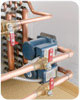
Fancoil units are designed to provide year-round comfort. (Photo
courtesy of IEC.)
DROPPING DT'S
Another concern is pressure differential within the system. As zone valves close, the system curve intersects the pump curve at higher and higher pressure differentials. This greater pressure differential can cause higher flow velocities within the system, and that can quickly lead to velocity noise. It’s the perfect hydronic storm: with a fixed-speed circulator, it’s easy to have poor heat transfer and inefficient, noisy operation, all at once.One way to deal with the noise would be to install a pressure differential bypass valve, which bypasses flow back to the pump suction and prevents excessive flow to the system when all of the heating zones are calling. But as those zone valves close, increasing pressure differential within the system, a smartly selected bypass valve can open to allow excess pressure and flow to pass through back to the suction (inlet) side of the circulator.
“A better solution for noise would be to use a mid-flow, low head, flat-curve circulator,” said Barba. “With such a pump, system pressure rises minimally, negating the need for a bypass valve. But, if the job has higher head needs than the circulator can deliver, use of a variable speed pump may be the best answer.”
With all of the zones calling, we know that DT = 75,000 ÷ 9 ÷ 500. So, the actual system DT at this point may be closer to 16°, not the 20° we designed for; that’s a full 20% difference. With only two zones calling, the DT drops to about 15° (a 25% difference), and with only one zone calling, the DT drops again to 12°, or 40% difference.
All of this can happen, even when it’s 0°outside. And if it’s 35° outside and the heating load at that temperature is only 38,000 Btuh with all zones calling, the DT disparity grows which can quickly lead to inefficient boiler short cycling and plenty of velocity noise.
According to Barba, application of a fixed DT, variable-speed circulator will solve the dilemma of dropping DTs.
“Looking back at the universal hydronics formula, we know that with the DT fixed at 20, and dividing the total load of 75,000 by 20 times 500 or 10,000, we find that the flow rate has to be 7.5 gpm. With two zones calling, a load of 50,000 Btuh, and a fixed 20° DT, we find that the flow rate has to be 5 gpm,” he said. “Clearly, with a fixed DT, flow will vary automatically to the zones, eliminating the risk of oversizing a pump. Rather than searching for the point where the system curve intersects the pump curve, we know that the pump curve will self-adjust every moment and every day of the heating season.”
In a variable-speed circulator, the DT control is built in. They’re simple to install and easy to program. There are no surprises during installation. The only difference is the need to wire the sensors on the supply and return.
Variable-speed circulators, by design, are also easy to set up. Simply dial-in the pump to meet the desired DT; it’s directly related to flow rate and part of the universal hydronics formula at gpm= Btuh ÷ the DT x 500.
Another pump control concept is Delta P (DP), or pressure differential. But where is DP in the universal hydronic formula? If what we’re trying to do is to satisfy the heat loss of the structure in the most efficient way, the ideal solution would be to allow the circulator to adjust its speed to deliver the required Btuh. By maintaining a consistent DT (10° for radiant, 20° for baseboard, higher for panel radiator systems, etc.), we can vary the flow as needed to ensure optimal performance and heat transfer.
One final thing about DT: it doesn’t flat-line. A DP circulator is always on, always drawing power, always maintaining a constant DP in the system regardless of what the system actually requires. If the programmed-in DP isn’t accurate, actual system flow rates may be much higher than required, and that will mean a smaller DT than designed, leading to less efficient system operation. A DT pump, on the other hand, will always run at the lowest possible speed, maximizing system performance and efficiency.
LARGER COMMERCIAL SYSTEMS
“Each piping system is a network; the more extensive the network, the more complex it is to understand, analyze, or control. Thus, a major design objective is to maximize simplicity.”- 2008 ASHRAE Handbook, HVAC Systems and Equipment,Chapter 12Hydronics is getting a new look by system designers who seek to design larger buildings to a new environmentally conscious standard. The technology provides ideal solutions by meeting two important goals: fewer materials used for the HVAC system itself, and less energy consumed during operation.
A recent development in commercial hydronic system design - the single-pipe series / decoupled system - meets both of these goals while providing superior comfort.
Oklahoma-based IEC is a leading producer of hydronic heating and cooling fan-coil units for a wide variety of commercial application. Along these lines, IEC produces a single-pipe hydronic system comparatively easy to design and install, which uses fewer materials and is nearly self-balancing.
A single-pipe primary loop is typically routed past a block of fancoils. These loop(s) may be configured horizontally or vertically as required by the layout of the building. Enhancements to these systems now permit effortless function of individual zones, opening up many opportunities in the commercial realm.
This system, which has a single-pipe primary main, uses terminal units configured with decoupled secondary circuits. Wet rotor circulators, tied to a thermostat to govern operation of each of many fancoil units (FCU), direct water through the local zone secondary system.
Simplicity is the hallmark of the single-pipe system. A conventional two-pipe system requires a supply and return pipe in the primary circuit, which requires more materials and naturally takes up more space. That can prove challenging, depending on the installation, if space is at a premium. A single-pipe system, however, has only one pipe to be installed, and that delivers both space and labor savings.
With the use of circulators, control valves aren’t necessary. And because the flow in all secondary circuits is independent of the flow in the primary circuit, there’s also no need for balancing valves at each FCU. By eliminating both types of valves, and having only a single-pipe primary circuit, the system is both simple in its design and uses far less material - on average 40% less pipe and fittings, no control valves and almost no balancing valves.
According to Ron Porter, LEED® AP, senior technical services manager at IEC, a single-pipe system also has lower head loss than a conventional two-pipe system, due to the elimination of control valves and balancing valves. Also, block-load operational diversity system design helps to reduce energy consumption in a single-pipe system.
According to Porter, these savings, plus reduced maintenance of the circulators, can significantly reduce the building life cycle cost.
The system IEC recommends is a series circuit with compound pumping. This concept is illustrated in its simplest form (Figure 2) with a single-pipe primary loop for cooling and a separate single-pipe primary loop for heating.
Chilled and hot water will flow continuously through these loops with pressure provided by central primary system pumps. Multiple cooling and heating primary loops are configured in parallel as required to feed separate buildings, floors, wings, or zones.
Local unit-mounted circulators cycle on and off, governed by the local room thermostat (traditional zone control valves are not needed).
While operating during periods of demand, the pumps borrow a portion of water from the primary loop, passes that water through an FCU, then returns the tempered water to a downstream connection on the same primary loop. The used water simply blends with the primary water which is then delivered to the next unit downstream.
Chillers and boilers are normally operated from secondary pumps, decoupled from the network of primary loops. The primary system pumps are selected for constant water flow with minimal pump head.
WHEN NOISE IS A CONSIDERATION
IEC’s single pipe configuration is ideal for application in commercial structures such as libraries and high-rise condominiums or in hotels where water velocity noise must remain below a specific threshold, typically 6 fps.A 2-in. copper pipe, for instance, has a limit of 60 gpm flow at about 6 fps and has a pressure drop at that rate of about 6 ft/100 ft of length. Given a target design water temperature rise of 8°, the connected load for fan coils may be established by this formula:
60 gpm x 8°x 500 = 240,000 Btuh or 20 tons
This pipe rating allows the engineer to make an initial design decision to connect no more than 20 tons of FCUs to a loop with 2-in. copper, with an initial temperature of 42° and a planned leaving temperature of 50°.
So, whether you’re designing a primary/secondary piping system with a single, variable speed, DT pump driving flow for zone valves, or a larger, single pipe, constant-pressure main to feed Btuh to a network of fan coil units, the likely result will be an optimized, energy efficient system free of complication. ES


