Figure
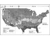
1. U.S.
climate zones chart from ASHRAE 90.1-2007, Appendix B. (Figure
courtesy of ASHRAE.)
When it comes to controlling humidity and minimizing the risk of mold, geography influences the strategy, and building pressure control is one area to focus on. See what one firm did to help a Louisiana hospital that was feeling the pressure in all the wrong ways.
In most instances, the primary concern regarding humidity in buildings is mold growth. Proper building construction and HVAC operation are the means for maintaining a healthy indoor environment. Proper indoor air conditions vary by building type and climate region, so let’s examine how the HVAC system is the key to controlling indoor humidity levels.
Understanding the Enemy
According to ASHRAE Standard 55, there is a temperature and rh range that should be maintained for human comfort. A good summer baseline in humid climate zones is an indoor condition of 72°F and 50% rh. There are also temperature and humidity ranges that must be maintained to prevent mold growth. Apropos, mold is more comfortable in the ranges outside of human comfort.Mold needs surface moisture and a food source to grow. Moisture prevention is the key to mold prevention. Improper moisture in a building can occur in one of three ways: 1) intrusion through the building envelope, 2) water leaks in the building, and 3) improper treatment of moist air through the HVAC system.
Designing For The Weather
Figure 1 shows a map of the United States and its various climate zones. The dashed line denotes the warm, humid areas. This map represents the primary scenario that engineers must utilize in their design at locations across the nation. Designs for buildings (including the envelope and mechanical systems) in Boston are much different than those for Houston because of the differences in outdoor air temperature and humidity.A corporation can build an office building in Boston and an office building in Houston. The street views of each may lead a person to believe that the buildings are identical, but they certainly should not be identical if they are to maintain proper indoor air conditions for human comfort and use energy efficiently.
The Boston building should utilize more insulation. It may or may not have a vapor barrier in the walls. It will require the same amount of fresh outside air for occupants as the building in Houston, but the air will require more heating. It may actually have air humidification for use in the winter because heating outside air from 10° to 68° produces an rh in the building of about 10%, which causes people to dehydrate much faster.
The Houston building will require much less insulation. The windows may even be single-pane, but they should be very resistant to solar gains. Fresh air will need to be air conditioned for the majority of the year. Humidification would only be required in a computer room application. Outside air would need to be cooled to at least 55° to remove water and then used to cool the building. Space temperatures would be maintained around 72° and the rh would be maintained below 60%.
Case study: A Louisiana Hospital
So, what happens if moisture infiltrates the space? If the building is under negative pressure (more air is exhausted through toilets, kitchens, and other areas than is brought in through the AHUs), moist outside air will come in through cracks in the building envelope and open doors. This moist air can easily condense on cold surfaces such as pipes or air diffusers. What results is surface moisture, which can allow mold growth.This was the case at a two-year-old, 60,000-sq-ft hospital building in Louisiana where SSRCx recently worked. What follows is an explanation of a negative pressure problem and a solution that was developed.
The outside air supplied through the AHUs could not function properly as designed and installed. The control strategy for the AHUs was a typical VAV system which modulates the supply air proportionally with the cooling load in the building. These AHUs were not designed to be able to maintain a constant volume of outside air when the main supply air modulates. There was no means for continuous measurement of the outside air (airflow measuring station), and therefore, no means to control it to the constant design volume. This was causing the building to operate under negative pressure much of the time, because the exhaust air was indeed constant. Luckily, mold had not begun to grow, but it may have only been a matter of time before the right conditions were met.
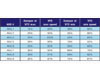
Table
1.
AHU
outside air damper settings and VFD speed.
The design outside airflow was properly set up at the maximum VFD speed. This steady-state condition produced a constant pressure differential between the outside air duct in the AHU and the true outdoor condition which could be measured with a handheld pressure sensor. This procedure was duplicated at the unit VFD minimum setting. The outside air damper was modulated until the same pressure differential at the maximum VFD setting was produced at the minimum VFD setting. Since the duct configuration did not change, the properties of airflow indicate that the volume of airflow will be the same if the pressure relationship is the same.
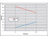
Figure
2.
An
example of an AHU-1 with damper reset and VFD speed.
Typically, VAV AHUs come equipped with an airflow measuring station that will measure and actively maintain a constant amount of outside air, regardless of VFD speed. The VAV AHUs at the facility were only equipped with a modulating outside air (OA) damper, and thus OA could not be directly measured and controlled. The OA damper was modulated in sequence with the VFD in order to maintain a constant flow of outside air through the VAV AHUs, and maintain total positive pressure in the building.
There is no guarantee that this will be 100% effective, due to pressure fluctuations from wind and other factors. The building pressure readings after this control scheme was implemented indicate that the building now maintains positive pressure, and subsequently, properly controls indoor humidity levels through the HVAC system.ES
