
Figure
1:
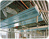
Chilled beams installed over the lab benches at the University of
Washington (UW) School of Medicine, South Lake Union Campus in
Seattle, capture the heat plume from the bench-mounted equipment.
(Photo courtesy of Ben Benschneider.)
Figure
2:
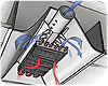
Active chilled beam installation. Note smaller-sized conduits. (Photo
courtesy of John Edwards.)
Research laboratories such as this fall squarely into a category of buildings in which the support provided by the facility and its mechanical and electrical systems is critical to the successful work of the building’s users. Innovative science requires innovative facilities. With a strong focus on energy efficiency - indeed, sustainability - in a building type known for high energy consumption, the use of chilled beam technology in this world-class science facility is itself a fitting innovation.
Figure
3:
Active chilled beam with the airflow increased by direct ducting of
supply air. (AEI Illustration.)
Chilled Beam Technology, Defined ...
The term “chilled beam,” which may seem to connote a structural device, is actually an efficient and sustainable HVAC technology that has been used in Europe and Australia for some time, primarily in commercial and academic environments.Simply put, a chilled beam is a convective cooling technology that can be configured as either a passive or active device to remove heat from a space. Mounted in an enclosure at the ceiling, a passive beam is essentially a chilled water coil that is able to generate air movement and cooling through convective currents created by warmer air rising in a space and colder air falling. Active beams are similar but have supply air ducted directly to them to increase the airflow through the device, thereby increasing its cooling capacity.
In essence, these devices transfer heat to and from the laboratory spaces by using a combination of water and air as transfer mediums. Given the greater physical capacity of water to move heat per unit volume relative to air, significantly smaller conduits are required than in a typical all-air system.
... And Applied To The Research Lab
The use of chilled beams in the laboratory environment provides opportunities to address many of the construction and operation challenges associated with these facilities, most prominently the need for large air-handling systems and ductwork and the substantial energy costs associated with laboratory facilities. Typical laboratories can have peak airflow rates in excess of 15 ach. Delivering this amount of air with a conventional air-handling system can drive the floor-to-floor height for these buildings to 15 to 16 ft (compared to 12 to 13 ft for a typical office building). The use of active chilled beams can reduce peak airflows to 6 ach or below, thus significantly reducing the size of equipment and ductwork, allowing the building to realize capital cost savings associated with a lower floor-to-floor height and significantly smaller mechanical rooms.
Figure
4. Active
chilled beam airflow pattern. (AEI Illustration.)
While other benefits such as lower noise, ease of control, and reduced filter maintenance all contribute to making this technology viable for use in the laboratory environment, it is not appropriate for every lab. Labs in which the size of the air-handling system is determined by the need to replace exhaust air from exhaust devices such as fume hoods are not appropriate for the use of this technology. However, equipment-intensive labs in which the air-handling system is sized based on the need to dissipate generated heat are prime candidates for chilled-beam technology.
Critical Testing Of Chilled Beam Technology
Prior to the announcement of the UW Medicine Phase 2 project, Affiliated Engineers, Inc. (AEI) had teamed with the National Institutes of Health through their Sustainable Design Initiative to identify ways to decrease energy use in the laboratory environment. With chilled beams identified as a promising technology, AEI developed a relationship with a major European chilled beam manufacturer to test several configurations of chilled beams in laboratories. Through a full-sized mockup process and extensive computational fluid dynamics (CFD) analyses, one variation of chilled-beam design was determined to optimize performance relative to benchtop loads while also accommodating maintenance access and the modular layout inherent in laboratory design today.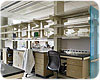
Figure
5:
UW Medicine Phase 2 finished lab with chilled beam placement directly
above the lab benches. (Photo courtesy of Ben Benschneider.)
Critical testing applied to UW Medicine Phase 2
As the building function became better defined early in the design process, it became clear that for much of the UW Medicine Phase 2 facility, building heat gain, rather than fume ventilation, would be the primary determinant of peak airflow rates, thus making the project a prime candidate for the application of active chilled-beam technology. Through an extensive series of discussions, presentations, and analyses, the design team - which included the University of Washington, Vulcan Inc., and architects Perkins+Will - adopted the use of the technology.As the design progressed, AEI and the team performed additional CFD analyses and full-scale mock-ups in the beam manufacturer’s thermal test facility to customize and fine-tune the proposed design, ultimately establishing further efficiencies in the technology, resulting in a reduction of capital costs.
Outcomes And Benchmarking
Completed in August 2008, the UW Medicine Phase 2 is among the largest laboratory applications of chilled beam technology in the world. While the potential for energy savings would be more pronounced in a climate less temperate than Seattle’s, the qualitative impact and overall sustainable design benefits to the facility are significant. The reduction in system support space requirements increases the net square footage of useable space, resulting in a greater degree of daylighting, and more pleasingly spacious labs. Lab spaces also benefit from lower ambient sound levels and greater uniformity of temperature and air movement.UW Medicine Phase 2 is adjacent to the first phase of the School of Medicine’s South Lake Union Campus, the adaptive reuse of Seattle’s locally known “Blue Flame” Building. The lab spaces and functions in the two buildings are closely comparable, though where UW Medicine Phase 2 employs chilled-beam technology, Phase 1 uses a more conventional VAV HVAC system. This offers ideal circumstances for ongoing benchmarking of chilled beam technology, of great interest to the A/E/C field as well as the beam’s manufacturers.ES
Sidebar: UW Medicine Phase 2: Chilled Beam Operation
Chilled beams at the UW Medicine Phase 2 project were configured to respond to the organization of the laboratory space with two 7-ft sections of beams located directly above the lab benches and a smaller 4-ft section mounted parallel to the outside wall. The beams mounted over the bench were positioned to effectively capture the heat plume from the bench-mounted equipment.A “one-way” throw beam was utilized to throw air toward the center of the aisle (a two-way throw configuration would have directed air into the storage boxes usually located on the top shelf of the lab benches). A one-way throw beam was also utilized at the exterior wall to provide adequate heat for the laboratory technicians with desk space at the exterior wall. Considerable CFD modeling and mock-up support was directed at this area during the design phases to ensure that comfort conditions were maintained without the need for baseboard convectors.
Primary air for the beams is provided through the central air-handling system serving the remainder of the building. This system delivers 55°F “primary” air to the beams through constant volume pressure independent supply air valves. The primary air is zoned to serve up to three laboratory modules.
In some areas of the building, chilled beams were not deployed for a variety of reasons:
- In many office areas the first cost of the beams relative to the potential energy benefit was minimal.
- One portion of a lab floor is slated for future chemistry research with associated high fume hood density that is not compatible with chilled beam installations.
- Other areas contained programs such as glass wash where high humidity levels increased the risk of condensation.
Heat for the labs is provided by reheat coils associated with the supply valve. A tempered water system provides cooling capacity to the coils in the chilled beam. The water is controlled to a temperature of 58° to optimize the capacity of the coil and prevent condensation from occurring on the coil surface. Redundant safety controls are incorporated into the tempered water system to ensure that colder water is not delivered to the beams, potentially causing condensation.
