
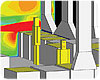
Figure
1A:
An isometric view of the coatings lab showing acid concentration at a
section cut over the tanks. Laminar flow diffusers are shown at the
ceiling as blue rectangles (yellow rectangles are lights). Tanks are
shown in gray sitting on the floor with gray exhaust ducts rising
behind the tanks. Two example occupants are shown in yellow.
Despite how the song goes, there actually is something like the real thing. Here, one consulting firm reports on its own use of CFD - when to deploy it, how to incorporate it in given situations, and what kinds of benefits it can yield. From identifying trouble spots in fume ventilation to making a school district more comfortable with committing to underfloor air, the advantages can add up.
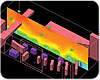
Figure
1B:
Close up isometric of an occupant in front of an acid dipping tank
acid concentration at a section cut over the tanks.
In addition, CFD can provide insights into flow problems that would be too costly or physically prohibitive to explore by experimental techniques alone. The insight and understanding gained from CFD simulations give added confidence to design proposals at reduced risk, avoiding the need to design by over-sizing and over-specification.
With ever-increasing awareness and concern regarding indoor environmental quality and all aspects of indoor perceived comfort, the demands placed on the HVAC system design require the design input CFD modeling can provide. As CFD software continues to advance, the benefits of CFD modeling utilization become increasingly apparent.

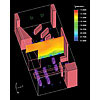
Figure
1C:
Close up isometric of an occupant in front of an acid dipping tank at
a section cut over the tanks.
CFD At SBEC
Shaffer • Baucom Engineering & Consulting (SBEC) engineers have used CFD modeling in a number of projects to generate airflow models that analyze critical and complex applications, including laboratory exhaust modeling and room ventilation effectiveness analysis for LEED® rating criteria documentation, hospital operating room airflow, atrium smoke-control systems, and building exhaust placement analysis. SBEC specifically used Airpak3.0, a CFD-based HVAC system design software program by Fluent, Inc. SBEC engineers have found that the software allows them to enhance documentation and communication between design professionals and customers, help minimize liability exposure, and deliver a superior product to the client.Airflow behavior in simple spaces with conventional diffuser placement is typically easy to predict, and air device performance data can be applied to conventional designs with a high degree of reliability. For complicated industrial applications and displacement ventilation applications where airflow is strongly affected by convection and other more subtle forces, computer-based airflow modeling becomes a very powerful design tool. The following material includes two case studies that illustrate the application of computer-based CFD software to model airflow in an industrial setting and in an elementary school media center.

Figure
2A:
An isometric view of the media center. Displacement diffusers are
shown in cyan arrayed across the floor, ceiling return grilles are
shown in green, shelving and other room massing is shown in gray and
light gray. A second floor walkway is shown near the top of the
image. Lighter colored masses represent computer tables.
CASE STUDY #1: Industrial Coatings Lab for an Aerospace and Defense Company
Space description. The coatings lab is 2,100 gross sq ft interior space, with no exterior walls or ceilings. The space has a 12-ft ceiling and includes a variety of workbenches and dipping tanks used for coating various manufactured parts. The primary process consists of 29 open-surface chemical-dipping tanks for anodizing, etching, dyeing, and hard-coating aluminum and titanium products. Some of the chemicals used in the Coatings Lab include sulfuric acid, nitric acid, hydrofluoric acid, and toluene.Tanks also offer chilling to temperatures of 55°F, heating to 165°, compressed air agitation, degreasing, deionized water rinse, and nitrogen drying. A circular crane rail is included for maneuvering parts over each tank and dipping. Also, a 4-sq-ft bench-top spray-paint booth is included in the space.
The coatings lab is served by a 100% outside air makeup air unit including 95% final filtration for supply ventilation air and space temperature conditioning. Supply air is introduced into the space at the ceiling level through distributed laminar flow diffusers located over the working areas of the occupants. Exhaust is provided by two sets of 100% redundant high-plume dilution laboratory exhaust fans. One set of exhaust fans provides exhaust air to two hydrochloric acid tanks and includes FRP construction of the fan and the entire exhaust-duct system including a specialty liner to handle the hydrochloric acid. The second set of exhaust fans provides exhaust to the remainder of the space, including all of the acid tanks. Each of the acid tanks includes a high-velocity, slot-type capture exhaust at each dip tank for acid fume capture.
Why CFD modeling? The application is an excellent case for applying CFD modeling analysis to the design process. The requirement for a full understanding of the room airflow dynamics to maximize the safety of its occupants is of primary importance. The Industrial Ventilation Manual published by the American Conference of Governmental Industrial Hygienists was used to develop the baseline exhaust flows at each dipping tank. Once the CFD model of the space was developed, several areas could be seen to have less than optimum fume capture, due to the complex geometries of the space, especially at the corner tanks. By using CFD modeling, SBEC engineers were able to model increased exhaust at various tanks in several different scenarios to optimize the acid fume capture for all tanks.
Performance. At the time this article went to press, construction was being completed and the dipping tanks were being populated. As operations start up, the airflow within the space will be reviewed to confirm the design intent.

Figure
2B:
Photograph of the media center with floor diffusers visible.
CASE STUDY #2: Elementary School Media Center
Space description. The space is a media center at a prototype elementary school in a school district south of Denver. The facility is a 73,000 gross sq ft elementary school designed as a high-performance building, utilizing a superior building envelope, daylighting design, and downsized HVAC systems. The media center is a 2,200-sq-ft interior space with a ceiling approximately 24 ft high (Figure 2B). Within the space are a circulation desk, a flexible arrangement of low book shelves, a reading area, and desk space for a number of desktop computers. Pendant-type lighting is provided, with both direct and indirect lighting. Daylighting is provided from an array of 15 tubular skylights at the ceiling.The room is served from a dedicated single-zone AHU located in the building crawlspace. A dedicated air-handling system was used to accommodate flexibility of room scheduling and to maximize energy efficiency. Displacement ventilation was used for the air distribution design, consisting of an array of 32 floor-level diffusers and ceiling-level return air grilles open to a return air plenum. Diffusers selected are cylindrical floor diffusers commonly used in underfloor air distribution systems. The selected “short-throw” diffusers deliver the supply air to the space with a degree of turbulence, which helps promote air mixing near the floor.
Figure
2C:
An east-west cross section of the media center, showing temperature
gradients from floor to ceiling in the cooling mode. Note the
floor-level temperatures and stratification. The relatively abrupt
transition from 70° temperatures to 72° temperatures occurs at
about 7 ft above the floor.
Why CFD modeling? SBEC offered CFD analysis for this and other spaces in this building for a number of reasons. First, this school design is a prototype design that has been applied five times to date and has the potential to be applied at several additional sites throughout the district. Secondly, this school design is the first true displacement ventilation design done by the school district. The CFD modeling results provided the owner with a level of comfort of the results without having to experiment or build a room mock-up. Lastly, the CFD modeling analysis assisted the design team with placement of diffusers, establishing supply air temperature settings, and helped determine the magnitude of the temperature stratification in the space, as there was concern regarding the air temperatures encountered at the second floor walkway through the media center.
CFD modeling analysis and results. The CFD model was performed in both heating and cooling modes. Supply air temperatures used are 65° in the cooling mode and 75° in the heating/morning warm-up mode. The resulting supply airflow rates are approximately 1 cfm/sq ft at maximum cooling demand. Figures 2C and 2D are cross-sections of the media center, showing the room temperatures from the floor level to the ceiling. Air velocities were checked as part of the analysis, and the CFD analysis confirmed the number of floor diffusers and the airflow range for each diffuser.
In addition, the CFD analysis assisted SBEC engineers in understanding the airflow movement from the diffuser locations to the areas of anticipated heat plumes where students may be congregated or where computer equipment may be placed. In this respect, the air delivery configuration allows the media center to be arranged in any number of ways, and there is a built-in allowance for as many as 20% of the diffusers to be covered by casework or shelving without any detrimental effects.
Performance. The media centers in the first of the prototype elementary schools have been operational for over a year, and the real-world performance of the rooms is very encouraging. The system is very quiet, the area is very comfortable, and the occupants have provided positive feedback. In addition, none of the shelving/furniture arrangements observed to date have covered more than 10% of the floor diffusers.
Figure
2D:
A north-south cross section of the media center, showing temperature
gradients from floor to ceiling in the cooling mode. Limitations of
the CFD program resulted in a diffuser throw pattern that is directed
more upward than the manufacturer’s data indicates.
Predicting the Future
Since 2002, SBEC engineers have been using CFD modeling to address complex airflow and heat transfer challenges encountered in virtually all types of HVAC applications. During this time, CFD software has evolved to provide HVAC design professionals increased ease of use, improved output, and faster processing. CFD modeling analyzes airflow and makes quantitative predictions to simulate the performance of systems whereas traditional testing methods require small-scale modeling and physical testing, which are expensive, time-consuming, and have physical limitations.The effort and costs involved with performing CFD analyses can be justified when compared to the benefits provided. In as little as a few days, SBEC engineers have information that assists with complicated designs, saves design and construction resources, and helps reduce design liability.
CFD produces comprehensive information to assess system performance, providing a means for greater design efficiency. In addition to these measurable benefits, clients and consumers benefit from peace of mind. CFD insights and confirmations instill confidence that the design decisions being made provide increased value to the client.
In short, today’s CFD software provides SBEC’s engineers with a comprehensive virtual modeling tool for predicting many types of airflow and heat transfer phenomena. With a growing variety of time-tested and proven tools, SBEC’s engineers are able to address, with confidence, a greater variety of applications and provide clients with a superior final product.ES


