
FIGURE 1. Internal equipment mezzanine showing AHUs. (Photo ©2008 Brady Architectural Photography.)
Pharmaceutical lab and plant design is complex enough, but adding time urgency driven by both municipal and product concerns can be a tough pill to swallow. Fortunately, exceptional teamwork and computer modeling avoided many potential complications and assisted this firm in achieving the cure for the common deadline.
On your mark, get set, go!
Fast track was an understatement when racing against the clock to bring a new $10-million San Diego laboratory and central plant online, thus allowing a mid-sized biopharmaceuticals company in San Diego to bring a new drug to market for Type II diabetes.Why the big rush? Essentially, two key elements drove the project schedule: one was the implementation of new building codes at the end of 2007, and the other was the need to have three large environmental chambers fully operational by the time their manufacturing facility was complete so that the new drug could be tested for quality.
The goal of meeting the first deadline was not to be able to design the building to a less-stringent building code standard, but rather to beat the expected influx of projects to the city that could potentially slow the review of this project to a crawl.
As for the second deadline, it involved designing, constructing, commissioning, and validating nearly 3,500 sq ft of environmental chambers while simultaneously constructing a self-supporting mechanical mezzanine and rooftop platform over the top of the chambers.
And if the time frame wasn’t enough of a challenge, the building team was charged with designing a 28,000-sq-ft laboratory inside a uniquely shaped existing high-bay warehouse that also included an existing second-floor office mezzanine. In addition, the design had to provide provisions for unknown future expansion capacity within the remaining 50,000 plus sq ft of open space.
Getting down to the task at hand, the team took a hard look at the space and infrastructure left behind by the previous tenant, most notably a large emergency generator pit next to the structure. With San Diego’s Miramar Naval Air Station nearby, the site, which is situated inside the “Accident Potential Zone,” represents the potential flight path for all aircraft coming and going from Miramar. Consequently, the local codes restrict the placement of any flammable materials on or above grade due to the explosion hazard. As such, the previous tenant had dug an approximately 20-ft deep pit, measuring 120 ft by 66 ft, to house five large emergency generators.
After extensive analysis of equipment size, cost, and lead time, it was decided to utilize an Aaon evaporative condensing packaged central plant located inside the existing pit. The engineers worked closely with the unit manufacturer to analyze the airflow patterns and unit location to ensure the proper operational requirements were maintained and that there would be no warranty issues.
Upon verification from the manufacturer, a single 245-ton unit was selected, with adequate space and infrastructure allotted for the potential placement of two more similarly sized units for future expansion. The plug-and-play unit is self-contained, including pumps, piping, expansion tanks, air separators, chemical treatment, ventilation, controls, and everything else needed to be a truly standalone central plant. In addition, the package was designed as a dual-circuited unit, which means half of the unit can operate while the other half is being serviced.
To help conserve potable water, the chiller utilizes municipal reclaimed water for the condenser water in the evaporative condenser section. Special chemical treatment, specifically designed for reclaimed water, ensures good water quality and limits the scale build-up on the wetted surfaces. To reduce water usage even further, the unit is equipped with a desuperheater located above the evaporative condenser section, which reduces water usage up to 20%, depending on the ambient conditions.
Although a unique setup, the pit turned out to be a great location in terms of security, distance from delivery truck routes, and noise control. In addition to the existing storm water sump pit, an extra condensate sump pit, complete with a duplex pumping system and controls, was installed for chiller condensate removal. As a result, there is sufficient space remaining in the pit for two more chillers and one standby generator if needed in the future.
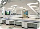
FIGURE 2. Lab underneath first floor mezzanine. (Photo ©2008 Brady Architectural Photography.)
Existing Conditions
Yet another space challenge was dealing with the warehouse’s high bay area, which meant more than 15 ft of ceiling space. While the other extreme involved trying to design laboratory space underneath a pre-existing second story mezzanine with less than 18 in. of ceiling space to work with.Although 15 ft of ceiling space sounds like a designer’s dream, when one is dealing with hanging ductwork and pipes in a large, open space under California’s strict seismic requirements, it is no picnic. Fortunately, 3-D modeling lent much assistance to the process of identifying hangar locations, seismic bracing, and clash detection. The modeling process enabled the design team to keep main ductwork and piping as high as possible, limiting the seismic bracing requirements, while keeping branch ductwork and piping low to maintain accessibility to important system components such as supply and exhaust valves, piping isolation valves, and electrical pull boxes.
As for the lab’s tight ceiling space, again 3-D modeling was used to coordinate duct crossings, utility drop points, valve accessibility and, of course, fire sprinkler piping and head locations. With less than 18 in. of ceiling space, every inch counted. Duct sizing and routing played an important role in getting all the required services to fit inside such a tight space.
Still another structural limitation was the fact that the existing roof structure was not designed to support the required HVAC equipment, so an internal equipment mezzanine that extended up through the roof was constructed. The new “superstructure,” as it was affectionately called, supports the boiler room, two 100% OA central air handlers, electrical distribution gear, transformers, and all the VFDs for both the air handlers and exhaust fans. In addition, the roof portion houses two Strobic Air Tri-Stack™ exhaust fans mounted on a structural plenum, a general exhaust utility set fan, and six environmental room condensing units with space left on the roof platform for future exhaust fans and/or other equipment.
Because vibration isolation was a key consideration for the air handlers and the exhaust fans, in order to limit the noise and vibration transmittance into the occupied lab spaces below, vibration isolators and sound attenuators were attached to all units.
Laboratory Controls
In addition to acoustical considerations, climate and IAQ for the laboratory area were key as well. As such, VAV Phoenix Laboratory valves and controls were utilized to maintain space temperature and pressurization. The system modulates down from design airflow to minimum required ach while maintaining a predetermined volumetric offset between the supply and exhaust to maintain room pressurization. Furthermore, minimum face velocity requirements are maintained for numerous fume hoods located throughout the labs.In the interest of saving energy, dual-pull occupancy sensors in every room control both the lighting and HVAC system. As for the latter, a special sequence of operations was written to enable the system to operate in occupied and unoccupied modes. When unoccupied, overall ventilation can be decreased by more than 40%, with the fume hood face velocity decreasing from 100 to 60 fpm.
The system’s emergency mode enables all the air valves to close to their minimum position, but still maintain a negative pressure in all the labs for safe occupant egress in the event of an emergency. The controls were also tested and balanced in their emergency mode to ensure that proper door forces will be maintained.
The laboratory control system ties into an existing Siemens BMS, via a gateway, allowing facility personnel to operate the laboratory controls from anywhere on their campus-wide network.
High Purity Water Filtration Skid
In planning for future use, a fully validatable, high-purity water filtration skid and piping system was designed and installed to supply 18-mega-ohm process water to the entire lab. In addition, the skid is capable of doubling its day-one capacity for future expansion as an additional storage tank can be tied into the system to increase the overall capacity.The system’s piping is sloped in such a way that it can be fully drained and then put back in service to minimize maintenance downtime and ensure high purity water quality. Similarly, b-polypropylene piping and IR butt-fusion welds are utilized to maintain the high-purity water requirement.
Other plumbing systems include a central liquid nitrogen system and a dual-source clean dry compressed air system: a central desiccant duplex skid and manifolded cylinders. Additional centrally piped utilities include CO2, helium, and nitrogen; all fed from a manifolded cylinder farm.
A separate lab waste system with a sample port was installed to allow the owner to test lab waste before it ties into the sanitary waste system.
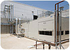
FIGURE 3. Chiller in large generator pit. (Photo ©2008 Brady Architectural Photography.)
Planning For The Electrical
In addition to the equipment storage pit abandoned by the former tenant - a Web-server hosting company, to the client’s delight - a robust electrical infrastructure was left behind as well.Plugging into the existing infrastructure, an expandable standby generator was designed to support growing capacity. The expandable system was also designed in a way that the addition of standby power capacity could be installed, tested, and brought online with minimal downtime.
Another challenge for the electrical design was to achieve the lowest light power density possible, while maintaining acceptable light levels at the laboratory benches. Through many computer-modeling iterations, the design team and San Diego Gas & Electric (SDGE) were able to lower the light power density to just under 20% better than T-24.
On The Sustainable Front
With energy-efficient design at the forefront of the program, not only does the lab well exceed ASHRAE 90.1 standards but it came in just over 15% better than California’s stricter Title 24 standards. Consequently, both the owner and design team are on track to cash in on a San Diego Gas & Electric (SDGE) “Savings By Design” incentive, which should amount to $14,000 and $4,500, respectively.The team’s collaborative design effort with SDGE also included premium-efficiency motors and variable-volume chilled and hot water pumping. Now, the owner is in the process of securing a 22,000-sq-ft photovoltaic system that will produce roughly 200 kilowatts of power for SDGE for onsite renewable energy.
Overall, the project is expected to qualify for a USGBC rating of at least LEED®-CI Silver, and possibly Gold, if all the points are accepted. Taking a look at the current rating card, the MEP systems comprise almost a third of the points, which include:
- More than 30% water reduction
- 15% below the light power density standard
- Optimized HVAC zoning
- Enhanced commissioning
- Outdoor air monitoring
- Increased ventilation
- System controllability
- An overall 15% better than California T-24
Keeping Up With The Schedule
But just how was it possible to pull together this highly sustainable lab project in such a short timeframe?Fortunately, the owner brought in all building team members, including the contractor and subcontractors, early on. As a result, these folks could offer critical input regarding constructability. Also, via design-assist, the contractors were able to provide pricing early on, before plans were submitted to the city.
Yet another boon to the process was an owner’s consultant who helped grease the wheels in terms of anticipating and planning for processes such as approvals for the stand-by generator. Furthermore, a commissioning team was brought in early on, to help troubleshoot and brainstorm.
Also, due to the unusual conditions of the existing space and tight construction schedule, 3-D modeling was employed by the contracting teams to help resolve conflicts and smooth the construction process.
As such, the mechanical contractor with the help of the design team led the 3-D modeling effort by combining all the subcontractor AutoCAD files into one central file, using NavisWorks, for clash detection and conflict resolution.
The process saved valuable time and money by eliminating both the often-lengthy RFI process and field changes that almost always arise during construction. It also helped identify alternate duct and piping support methods in the high-bay areas to meet stringent California seismic requirements, as mentioned.
Now, after a time-efficient and dedicated effort, construction is very near completion, although the labs will be going through a lengthy validation process prior to occupancy scheduled for later this year. But when the client moves in, they should find a state-of-the-art, highly sustainable laboratory facility waiting to support and expedite their drug validation and speed to market processes.
The success of the project could not have been accomplished without the collaboration of Syska Hennessy Group, Ferguson Pape Baldwin Architects, GSSI Structural Engineers, DPR Construction, University Mechanical, and Berg Electric.ES
