
FIGURE 1. A cutaway diagram of the active chilled-beam system.
The 250 South Wacker building reportedly houses a first for American HVAC installations. That might sound exotic, but as you’ll see, the author delivers the story behind this retrofit in a matter-of-fact manner that belies the step forward taken by the owner and project team. Da beams may never be quite as popular as Da Bears in Chicago, but they’re bound to spread as other project embrace the concept’s advantages.
The active chilled-beam system installed at the 250 South Wacker building in Chicago is the first operational chilled-beam system in the country. The system uses less energy than traditional systems, since its fan horsepower requirements are very low, and the water systems do the majority of the comfort work.
The system eliminates IAQ issues, since outside air (primary air) is delivered in constant flow to each chilled-beam unit. Also, a multiple of four times primary air is circulated in the room by the chilled beam. There are no drafts, hot/cold spots, or odors from construction glues, paints, etc., as issues for occupants to deal with.
Maintenance personnel are happy with the system since there are no moving parts. Once construction adjusts and calibrates the system, maintenance has a coil to clean once per year.
This downtown, 17 stories, 270,000-sq-ft, 50-year-old office building on the Chicago River underwent a full modernization to bring it up to today’s state-of-the-art office building standards.
The subsequent HVAC system modernization included a perimeter chilled beam system - a first for the nation as well as the city.
When 'Plan A' goes awry
The original perimeter HVAC system for the building was a wall-mounted induction system with no condensate drip pans. At the start of the remodeling projects, it was decided to dismount the induction system, clean/patch coils, clean the rubber nozzles, and paint the 50-year-old cabinets. It soon became obvi-ous to the team that this option was, in fact, not an option at all. Soon thereafter, parts and pieces began falling apart regularly.
FIGURE 2. An active chilled beam system allows 250 South Wacker Drive in Chicago to use 40% of the air volume of a standard system.
The ceiling-active chilled-beam system, as presented by Mestek, Inc./Dadanco, seemed to fit the bill. The system uses minimum energy, has no moving parts, requires minimum maintenance, is ceiling-mounted, and met the construction budget. The only issue was that there were no example sites for the team to visit.
In order to resolve this issue, the team reviewed a number of chilled beam units, analyzing construction, and installing the samples. Upon successful comple-tion of this analysis, it was decided to proceed with the chilled beam design and installation by the team. The results are a system which looks great, functions perfectly, and satisfies the green / energy conservation goals of the project.
The system
Chilled-beam systems are primarily used for cooling, heating, and ventilating spaces where good indoor environmental quality and individual space control are desired. The units are connected to the ventilation supply air ductwork and the two-pipe heating and cooling system.Two central AHUs supply primary air (conditioned and dehumidified outside air) to the offices through the ceiling chilled-beam units. The primary air induces room air to be re-circulated through the coil of the chilled beam. Room air temperature is controlled by the water flow rate through the coil.
Active chilled-beam systems may be an ideal green solution for many buildings. They easily meet the energy-efficiency requirements of the Federal Energy Policy Act of 2005. The design supports sustainability since the central air-handling system circulates only the amount of air needed for ventilation and latent loads. The active chilled beams provide the additional air movement and sensible heating/cooling required through the induced room air- and unit-mounted secondary water coil.
Thus, as compared to all air systems, primary air volumes are dramatically reduced. Indeed, the building system in 250 South Wacker uses 40% of the air volume of a standard system. The chilled-beam system transfers the majority of heating and cooling loads from the air distribution system to the water distri-bution system. This is because the use of the water distribution system for the majority of heating and cooling loads is more efficient than the use of the air distribution system.
The result is that the chilled-beam system uses less energy with lower operating costs. Remember, the chilled water return and hot water return flows become the supply flows to the chilled-beam secondary coil. So, maximum use of the energy generated by central plant is transferred to the building.
The technology
How does the active chilled beam work? Referring to Figure 1, primary air (1) is introduced into the active chilled beams through a series of nozzles; (2) room air is then induced; (3) up into the active chilled beams’ coil; and (4) the induced room air is cooled or heated by the water coil, as necessary, to maintain room temperature. The induced room air is then mixed with the primary air (5) and is discharged into the room. The water control valve is thermostatically controlled (6) to maintain setpoint.Occupants experience comfort through excellent and uniform air movement and temperature. The induced air is typically three to four times the primary air volume, and the flow is constant. Air temperatures are moderate, generally 60s for cooling and 80s for heating. The result is no cold air dumping and no drafts.
IAQ and odor control are never an issue since full ventilation air requirements are delivered to each unit. This occurs continuously at all load conditions dur-ing the occupied cycles.
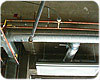
FIGURE 3. 250 South Wacker Drive is a shell-and-core design and piping is arranged to allow individual control of each chilled beam.
In action
At 250 South Wacker, the two primary AHUs operate continuously during the occupied cycle. Duct static pressure sensors maintain +0.6 in. w.c. of air pres-sure to the farthest chilled beam units.The supply air from the primary AHUs is 50°F drybulb. This removes large latent load from the primary air. The air is then tempered to 58°. Thus the primary air sup-plied to the chilled beam is dry and above dewpoint temperature. During the economizer cycle, at the primary AHUs, sensors check to ensure that the ambient dewpoint is 52° or lower.
Three-way valves divert the building’s chilled-water return system to supply water to the chilled beams’ coil. Thus the spaces’ sensible loads are satisfied. The chilled water leaving the active chilled beam’s coil is returned to the 850 tons of central chillers.
During the heating season, the primary AHUs are supplied hot water from the steam-to-water heat exchanger. The building’s hot water return is supplied to the chilled beam coils. Entering water is 140°. Leaving water can be as low as 105°.
The BAS controls the HVAC systems. Dewpoint sensors are dispersed throughout the building, monitoring the temperatures. It is important to maintain a 3° to 5° spread between the systems’ fluid and air temperatures, as compared to ambient dewpoint temperatures.

FIGURE 4. The chilled beam system is integrated into standard ceiling tiles and are placed within 18 in. of the perimeter building skin.
The existing building HVAC system was already equipped with both vertical water risers and duct air risers at perimeter columns, which made ceiling active chilled beams a natural system choice for the project. The fact that the vision glass extends from structural column to column (and from overhead girder to floor) simply rein-forced the decision to keep the mechanical system off the occupied rentable floor space.
The building is a shell-and-core design; therefore, the piping is arranged to allow individual control of each chilled beam, or depending upon office space planning, control groups of active chilled beam units. Primary air to chilled beams from the duct air risers are equipped with dampers for the balancing of airflows to the active chilled beams.
In order to more closely match the diverse year-round heating and cooling loads and to assist in testing and balancing, VFDs were added to the existing pri-mary AHUs.
Two small natural gas-fired boilers (one is standby) with eight duct-mounted hot water coils were added to the primary duct distribution system. These coils are in-tended to temper the primary air supplies to the chilled beams from 50° to 58°. The coils ensure that the primary air supplied to the chilled beams is always above dew-point temperature.
The outcome of this active chilled beam design is a green, eco-friendly building. It provides excellent thermal comfort, energy conservation, and efficient use of space. The system operation is trouble free, simple, and has minimum maintenance requirements.
The system provides constant airflow mixed with balanced conditioned outside air to each chilled beam. Thus there will be no IAQ issues. The end result is a successful project and satisfied client.ES
