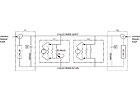
FIGURE 1. Interconnection of two variable primary plants and two load groups between the plants.
What determines chiller plant loading? Do connected plants need to use similar pumping schemes? Is it better to run one chiller in multiple plants or multiple chillers in one plant? Draw on the author’s experience for answers. Then learn how to handle the hydraulics of interconnection and enjoy the byproducts of a well-integrated system.
There are situations in commercial, institutional, and industrial facilities where it is advantageous to interconnect independent chilled water plants. Examples include:
- A facility expansion where the existing plant is land-locked and additional capacity must be built elsewhere.
- A campus environment where plants in several buildings are oversized or have redundant capacity that could be shared to improve overall reliability.
- Multiple plants where some are more efficient, have a more favorable electric rate, or could be operated closer to their sweet spots to achieve lower annual operating costs
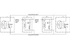
FIGURE 2.Interconnection of two variable primary plants between two load groups.
This article describes what interconnection factors are important to consider in order to achieve a happy customer. Our experiences were developed from several projects including a hospital expansion project, a pharmaceutical manufacturer with separate plants, and the addition of a satellite plant to a large downtown district cooling system.
Interconnection Methods
The interconnection can be done between two or more chilled water plants serving one or more load groups. A load group is a collection of chilled water users (air handlers, fancoils, process equipment, each with a two-way control valve) located in portions of a building or multiple buildings. Several criteria must be met:- The supply water temperature delivered to the load groups must satisfy the lowest requirement. If one load group has a lower design supply water temperature, all plants may need to operate at this lower temperature.
- The static pressures imposed on the load groups and chiller plants must be compatible. All parts of the systems must be rated for the highest pressure that they will experience.
- A networked control system must be provided that can pass information between plants and load groups.
Figure 2 shows an interconnection among two adjacent plants and two remote load groups. Figure 3 shows an interconnection among two plants and two load groups, each with local variable-speed booster pumping. Other interconnection configurations are possible. The best configuration may be decided by the facility layout, constructability issues, timing of growth, cost, or other factors.

FIGURE 3. Interconnection of two variable primary plants and two load groups which each have booster pumps.
If the distribution pumps in one plant do not have sufficient head to get the chilled water to hydraulically remote load groups, then that plant may not be able to load to the desired level when operated in conjunction with other plants or may fail to meet all loads when operated alone. A hydraulic network model or other calculations should be performed to gain understanding of the distribution system, the required pump heads, and the required size of the interconnecting piping.
Perhaps surprisingly, the plants do not need to have the same pumping scheme. Some plants can be variable primary while others are primary-secondary, as shown in Figure 4. Each plant appears to the load groups as a variable-flow source of chilled water. The internal-plant method of chiller flow control is not a factor with respect to the load groups. It is a factor in how individual chillers are enabled and disabled.
When plants are interconnected, the hydraulic analysis should be used to determine the expansion tank size and connection point, the makeup water connection location, relief valve locations, and system static pressures. For simplicity and cost, the interconnecting piping between plants is usually left open on both the supply and return mains, no matter which plants are operating (no automatic isolation valves). The distribution-pump check valves or chiller isolation valves (if there are multiple chillers within a plant) are relied upon to prevent short-circuiting of supply to return via the idle chillers. The open pipe paths allow expansion tanks and makeup water valves to be located in one spot, achieving economy of scale and easier maintenance.
A redundant makeup water source in another location may be desirable. The chemical feed location should be located near the primary makeup water connection so that the chemicals can better treat the makeup water at its source. Relief valves should be located wherever manual or automatic valves could isolate a section of pipe or equipment.
Bypass Path Location
In variable primary pumping schemes, a bypass path must be provided to allow adequate chiller flow when loads are low. In a single-plant configuration, we prefer to locate the bypass as far from the chiller plant is possible, usually at the point in the distribution system where the pipe mains have reduced down to where they are the same size as the bypass pipe. This location provides a larger reservoir of water in the system that can help buffer changes in the chiller load when flows change and avoid shutdowns due to low evaporator temperature.(As a side note, the buffering effect is dependent on the dynamics of the chiller compressor control loop and the bypass valve control loop, the shape of the distribution-pump curve, and other factors. The buffering effect of a distant bypass path is not guaranteed, but intuition leads us to think it is better than a nearby bypass.) As in any variable primary system, the safest strategy is to limit the rate of change of the terminal control valves so the chillers do not see a rapid flow change.
In a multiple-plant variable primary configuration, more than one bypass may be required - usually close to each plant. If Plant P1 has low chilled water flow and its bypass is distant and close to Plant P2, opening the bypass may satisfy the flow needs of Plant P1, but the load on Plant P2 will fall.
There is no way to increase the load on Plant P2 (such as speeding up its distribution pump) without stealing flow from Plant P1. As described later, this may violate the control objective for the plants. Therefore, each plant needs a bypass located close by, to which it has easier hydraulic access than any other plant. The location will depend on the plant and load group configuration. The bypasses can be located far from each plant if the system configuration is like Figure 5. The bypasses must be close to the plants if the configuration is like Figure 1.
Interconnected Plant Operation
How should interconnected plants be operated? One strategy might be to have all active chillers in all plants operate at the same percentage of full load (e.g., each active chiller is loaded to 60% no matter what its size, if that is what it takes to meet the campus load). A different strategy might be to heavily load the most efficient active plant as long as the other active plants stay above their minimum load. The best control strategy depends on utility rates, equipment efficiencies, and other factors, but any loading strategy (uniform or preferential loading) can be implemented following similar principles.What determines chiller plant loading? Chiller plant loading is determined by the distribution pump speed: for a given return-water temperature, increasing the plant’s pump speed increases the plant loading; decreasing the pump speed decreases the plant loading.
Interconnected plants must satisfy both the plant-loading strategy and the load-group demands. For example, assume there are two active plants (P1 and P2) of equal capacity, a uniform plant loading strategy, and two load groups (L1 and L2), each with a nearby differential pressure sensor. Plant P1 is arbitrarily designated as the primary plant when both plants are running. Its distribution pump is operated to satisfy the load group differential pressure sensor that is furthest below setpoint.

FIGURE 4. Interconnection of variable primary and primary-secondary plants.
If the strategy is to load Plant P1 as high as possible, then its distribution pump is still operated to satisfy the load group differential pressure sensor that is furthest below setpoint. If Plant P1 is at 70% load and Plant P2 is at 60% load, the speed of P2’s distribution pump will decrease. This will undersatisfy the load group differential pressure sensor, causing the speed of P1’s distribution pump to increase. Plant P1’s load may increase to 72% while Plant P2’s load decreases to 58%. This process continues until Plant P1 is loaded to 100% and Plant P2 is loaded to 30%. If the minimum allowable load on Plant P2 were 40%, the adjustment process would be stopped sooner (when Plant P1 is loaded 90%).
To provide stable operation, the pump speed adjustments to satisfy the load-group demands should happen more quickly than adjustments to satisfy chiller plant loading. Chiller plant loading is a less important criterion.
Chiller Plant Start-Up Issues
When Plant P1 is serving all load groups and the plant sequencing logic determines it is time to start another plant, Plant P2 must be started in a way that does not cause Plant P1 to trip off-line (tripping does not make for happy customers). The start-up procedure must not cause low water temperature in Plant P1 (due to a sudden loss of flow). It must also quickly place enough load on Plant P2 so it does not shut down after a few minutes. A way to accomplish this in variable primary plants is:- Start Plant P2’s chilled water pump at a minimum speed (determined from field observation during commissioning). Plant P2’s bypass valve will automatically open as necessary to maintain the minimum flow through the Plant P2 chiller. The flow caused by the Plant P2 distribution pump will be almost entirely short circuited within Plant P2 and will have little effect on Plant P1 or the load groups.
- Once the minimum chilled water flow has been achieved, start the chiller in Plant P2 and initiate operation of the plant-load-balancing algorithm. The speed of the Plant P2 pump will increase to cause Plant P2 to pick up more load. Plant P2’s bypass valve will close. Plant P1’s flow and load will decrease

FIGURE 5. Bypass paths distant from the chiller plants.
We have found this to be a better solution than the practice advocated by others of limiting the output of the active chillers on start-up (sending the chiller a demand-limit signal, which commonly cannot be less than 40% on most chillers). Why? If chillers A and B are running at low load (say 50%) and chiller A fails, the output of chiller B can’t be lowered much further by demand limiting. When the valve opens on the back-up chiller C, the flow to chiller B will be cut by a third, possibly causing it to trip on low water temperature. This assumes the isolation valve stays open on chiller A for 2 to 3 min to dissipate residual liquid refrigerant in the evaporator (for freeze protection). By slowly opening the valve on chiller C and slowly closing the valve on chiller A, chiller B has time to adjust the compressor output and avoid a trip.
In general, for efficiency reasons, if each chiller plant has more than one chiller, it is better to run one chiller in multiple plants rather than multiple chillers in one plant. This places more cooling tower surface area and more pipe capacity in service, resulting in lower power for cooling tower fans, condenser water pumps, and chilled water pumps.
