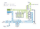
FIGURE 1. Chilled water plant piping schematic.
Chiller plant retrofits are common. Reliability issues created by using water brought in from the Tidal Basin are not. An existing system involving a special vacuum priming system and a chilled-water jockey pump isn’t exactly commonplace, either. Then you have the chemical treatment concerns since the conditioned space houses priceless artwork. Return with us to the National Gallery of Art to see an interesting design for a project framed by a number of unusual restrictions.
Imagine a place where the temperature and humidity will be exactly the same every day. No rain. No snow. No “scorchers,” ever. Well, there is a place where ideal conditions of clean air, consistent temperature, and rh are maintained around the clock for its occupants. And you are cordially invited to visit. Often.
Welcome to the National Gallery of Art (NGA), one of the most highly respected caretakers of some of the world’s greatest artworks. Thousands of the country’s national treasures - paintings, sculpture, decorative arts, and more - are housed and cared for by NGA within the gallery’s more than one million sq ft of space. The collections, which are viewed by an estimated four million visitors a year, are housed in the gallery’s two prominent buildings, which are conveniently located on the National Mall in Washington. The buildings themselves are considered works of art, designed by two architectural giants of the twentieth century, John Russell Pope (the West Building) and I.M. Pei (the East Building and its connecting link). The doors at NGA are open virtually every day of the year - except December 25 and January 1. The National Gallery’s mission statement reflects how seriously it regards its mission in preserving our cultural heritage:
The mission of the National Gallery of Art is to serve the United States of America in a national role by preserving, collecting, exhibiting, and fostering the understanding of works of art, at the highest possible museum and scholarly standards.
One of the key components in preserving the gallery’s art works is maintaining an indoor environment throughout the galleries at ideal conditions for its irreplaceable art treasures: generally at 70°F and 50% rh. Keeping these indoor conditions consistent every hour of every day depends on a reliable supply of chilled water. Recognizing its stewardship responsibilities for preserving and protecting this massive collection of priceless and irreplaceable examples of man’s artistic expression, the gallery’s administration began a lengthy and complex process in 1997 to ensure future generations the joy of appreciating NGA’s ever growing collection by instituting upgrades of its critical support systems.
Designing For The Future
A master facilities plan (MFP) was developed to identify issues related to facility aging, and to plan for the orderly replacement and renovation of engineering systems that provide critical support of the gallery’s operation.The MFP identified 14 work area projects as well as a number of central plant projects. Execution of the MFP is well underway. The following projects are now complete: Work areas 1 and 2, West Building electrical upgrade, and chiller plant renovation. Work Area 3 and the emergency power supply system projects are now under construction.
In addition to other MFP work, Hayes, Seay, Mattern & Mattern, Inc., was selected to perform engineering studies and then to design the chiller plant renovation. NGA’s Office of Capital Projects (AOCP) oversaw the design and construction, coordinated with outside agencies such as the federal government’s General Services Administration (GSA), and coordinated construction impacts within the National Gallery organization.
Environmental And Service Life
When the MFP was developed, the gallery’s chiller plant had in place, two 1,250-ton centrifugal chillers originally installed the early 1970s, and three 700-ton centrifugal chillers installed in the early 1980s. These machines were nearing the end of their expected service lives. Further, they operated with refrigerant R-12, which had been phased out of production in 1996 due to environmental issues concerning ozone depletion. NGA decided to update these older chillers with a new, more efficient, and environmentally friendly system. The updated approach eliminated problematic refrigerant supply issues with the older units, thereby enhancing NGA’s chiller plant reliability.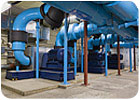
FIGURE 2. Utility water pumps and pipe headers. These pumps supply the cold side of heat exchangers during normal operation and chiller condenser during standby operation.
Condenser Cooling Water
Another issue facing chiller reliability was the continued use of water drawn from Washington’s Tidal Basin for once-through condenser heat rejection. The Tidal Basin system - originally built in the 1920s - was created to supply condenser water to a number of federal buildings to avoid aesthetic and practical problems related to operating cooling towers in downtown Washington. Water from an inlet at the Tidal Basin flowed by gravity through underground arched waterways and piping to various buildings located along Constitution Avenue. After this water completed its task of cooling condenser units, it was discharged to the city’s storm sewer system. Some 80 years later most of the original users had installed their own cooling towers and disconnected from the Tidal Basin system due to a variety of problems, including the system’s age/reliability, poor water quality (suspended debris and biological materials), and high intake temperatures.As studies were conducted on how to configure the NGA chiller plant renovation, the nearby National Archives was being renovated. Its leadership chose to disconnect from the unreliable Tidal Basin supply, leaving NGA as the only remaining user. In addition to the high maintenance requirements on strainers and condensers, NGA was concerned about a potential catastrophic failure of the system beyond its control, as well as with the possibility of problems with future renewals of its discharge permit.
Mechanical Complexity
NGA uses air washers to condition the air that is distributed throughout the facility1. Air washers spray chilled water directly into the airstream, resulting in an open system that requires chilled water to be returned to the supply source for recirculation either by pump or gravity. Water returned from NGA’s two gallery buildings feeds into a single chilled water pit. Since the original chilled water pumps were horizontal split-case type, located on the floor above the water level in the pit, keeping the pump primed required a vacuum priming system as well as a chilled water jockey pump. This arrangement made the system more complex and lowered its reliability.GSA As Chilled Water Provider
During the initial concept design of the plant renovation, the GSA was renovating its chilled water plant near the Mall2and improving its chilled water distribution loop. The GSA, Smithsonian Institution (SI), and NGA began discussions about using excess capacity in the loop. The talks led to a Memorandum of Agreement (MOA) whereby GSA agreed to supply chilled water to NGA.There are a number of special considerations that NGA’s chilled water has to meet, largely due to the air washer process, in which the chilled water becomes, essentially, a part of the airstream. This eliminated the option of using GSA’s chemically treated chilled water directly in the NGA system. The concern was that the chemicals would contaminate and damage the art. But the GSA chilled water supply could still play a critical role in the new NGA system.
GSA Chilled Water As A Coolant
To maintain the required temperature and humidity conditions in the galleries and art storage areas, NGA’s chilled water has to be supplied at 42°. Because the air washers are cross-flow heat exchangers, return water temperature cannot be higher than the leaving air. The resulting chilled water temperature differential can only be 6° or 7°. This relatively low temperature difference results in flows that are two to three times higher than those in most commercial chilled water systems. GSA was willing and able to accommodate a low supply water temperature, low temperature differences, and high flows at their central plant.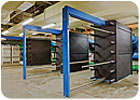
FIGURE 3. Plate-and-frame heat exchangers are used to separate NGA’s open chilled water system from chemically treated utility GSA-supplied chilled water.
Making It All Work: The Renovated Plant Configuration
The renovated chilled water plant configuration is shown in Figure 1. The NGA chilled water plant is designed to use GSA chilled water (utility water) to cool the NGA chilled water system. In order to isolate the chemically treated closed GSA system from the open NGA chilled water system, the two systems are separated by plate-and-frame heat exchangers with a 1° approach. GSA delivers supply water at nominal 41°, allowing the NGA system to operate with its design condition of 42° chilled water supply.The plant is sized for an ultimate load of 3,000 tons, with a current operating limit of 2,400 tons as stipulated in the MOA. Utility water pumps circulate GSA chilled water through heat exchangers. During standby operation the utility water pumps circulate water through the condenser of the standby chiller.
Primary chilled water pumps move water from the storage pit through either the heat exchangers (normal operation) or chiller (standby operation). Vertical turbine pumps were selected for primary pumps to avoid pump-priming issues that had plagued the previous plant. Secondary chilled water pumps then distribute chilled water throughout the entire NGA complex. Booster pumps in the East Building elevate chilled water to the upper floors and connecting link. Transfer pumps return chilled water to the chilled water pit, where level control valves throttle the transfer flow to maintain pit level.
VSDs are provided on the primary chilled water pumps, secondary chilled water pumps, utility water pumps, and booster pumps to match water flows to actual building loads. The standby chiller will supply chilled water if the utility fails or cannot deliver supply water at a low enough temperature.
The chilled water plant has three basic operating modes: normal, standby on utility water, and standby on domestic water. During normal operation, the primary chilled water pumps circulate chilled water through the heat exchangers. This chilled water is cooled by utility water circulating through the other side of the heat exchangers.
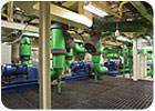
FIGURE 4. Secondary chilled water pumps are used to distribute chilled water throughout the NGA complex.
If utility water flow is not available, the NGA system can be indexed manually to operate on domestic water. A new 12-in. domestic water feed has been installed to accommodate this mode. During operation in this mode, the primary chilled water pumps circulate chilled water through the standby chiller. The chiller’s rejected heat is then cooled by domestic water admitted to the utility water loop, and wasted to the storm drain.
Pumps and heat exchangers are provided in an N+1 arrangement (typically three at 1,500 tons each) for redundancy. This means that if a single piece of equipment fails or is taken down for service, the remaining equipment can handle 100% of the load.
Typically, this is accomplished in a lead-lag-standby arrangement. These designations rotate weekly to equalize run time. At low loads, the lead piece of equipment is energized. When the load exceeds what a single piece of equipment can provide, both the lead and lag pieces of equipment are energized. If there is either a lead or lag equipment failure, the standby equipment takes its place.
The chiller plant is controlled and monitored by the NGA BAS, which provides direct digital control of a custom programmed, complex sequence of operation.
Construction
In order to select a construction contractor, NGA went through a “best value” process where both price and technical qualifications were evaluated from a number of excellent proposals. NGA selected Poole & Kent of Baltimore, as construction contractor for this project.The most important consideration during construction was maintaining continuity of temperature and humidity in the galleries and other spaces housing artworks. The air washers have an airside economizer for winter operation, but chilled water must be available any time that the outdoor wetbulb temperature exceeds 48°. Chilled water outages for the cutover were scheduled based on weather forecasts. Contingency plans were developed to restore chilled water in case the weather changed or the cutover activity took longer than expected. The planning approach was to avoid major construction during summer months when the cooling load was near peak.
Initially, the two existing 1,250-ton machines were removed to make room for installation of the new 2,000-ton standby chiller. Once the standby chiller was operating, the three 700-ton machines were removed sequentially. Heat exchangers were installed in their locations. During this same time, pumps and piping were being swapped out and the chilled water pit lid was replaced with one capable of supporting the new primary chilled water pumps. This construction sequence required parallel operation of new components as well as the legacy equipment, resulting in a very complex and challenging “shell game” construction sequence.
The original construction sequence anticipated the standby chiller as the only source of temporary chilled water during installation of the heat exchangers. However, delays caused this activity to slip to the summer, raising concerns over this potential single point of failure. At that time, one heat exchanger was installed in a temporary location to provide cooling, augmented by a trailer-mounted rental chiller. The temporary equipment was connected into the NGA system via multiple 8-in. hoses. After two of the heat exchangers were online, the third was moved from its temporary location to its permanent one, and the rental chiller was removed.
The plant was commissioned and substantially complete in the spring of 2007. Trending and extensive monitoring of operations were conducted by AFM, NGA’s facility maintenance group. As expected in a system as complex and dynamic as NGA’s, a number of startup issues surfaced due to this careful monitoring. However, these were quickly accessed using trend data available from the NGA BAS. Most issues were corrected by fine-tuning control parameters to match the dynamic nature of the system.
The summer of 2007 was the renovated chiller plant’s maiden cooling season. This technically challenging and complex project has resulted in a system that has proven to be flexible and robust in meeting NGA’s chilled water needs reliably and with a significantly reduced maintenance burden over the previous plant. Meticulous planning, coordination, and cooperation of all parties resulted in the successful culmination of this project without significant interruption to NGA’s normal operation, and without exposing the art collection to risk. This system will play a significant role in preserving our nation’s treasures for years to come.ES
Cited Works
1. Witt, Calvin L., “Timeless Art, Timely Engineering,”Engineered Systems, May 2005.2. Turpin, Joanna R., “For the People: Government Chillers Keep Costs Cool,”Engineered Systems, October 2003.
