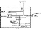
FIGURE 1. Panel-mounted HOA potentiometer sample wiring.
From BAS control panel wiring to network configuration, what we have here is a concise but thorough overview of what sets the BAS design and process apart in these special applications. Effective controls in this category require a different approach for power supply, documentation, and monitoring, so read on to avoid testing the fault tolerance in people as well as systems.
While comprising a critical component in mission critical facilities, BAS oftentimes get overlooked. BAS provide critical data and control for facilities. The Uptime Institute has developed a tiered classification model that is used by designers and owners when developing data centers capabilities.
Tier I data centers have no redundancy, while a Tier IV data center is full of redundant power feeds and electrical systems and adheres to a fault-tolerant design model. While the BAS has a direct impact on data center performance, it is not directly correlated into the tier classification. Standard BAS concepts do not require fault-tolerant design strategies, nor are they cost prohibitive. Mission critical BAS do need to adhere to some form of fault tolerance in order to ensure system downtime is minimal or nonexistent.
Fault-Tolerant BAS Concepts
The basic concept of fault tolerance is the ability to handle system failures whether they are internal to the system (e.g., scrambled program) or external (e.g., loss of control power). Similar to the tier classification model developed by the Uptime Institute, when designing mission critical BAS, different classes of fault tolerance can be implemented. The classes are panel layout and construction, system design, and advanced network architecture. The fundamental class for fault tolerance is proper panel layout and construction followed by proper system design and finally, for ultra critical applications, advanced network architecture.
FIGURE 2. An example of redundant controller wiring.
Panel Layout And Construction
A mission critical BAS relies heavily on maintainability, moreso than a typical BAS. Proper panel layout and construction increase system sustainability. However, it is not unusual to find a mess of wires when looking inside a BAS panel, which adds confusion when troubleshooting and has the potential to cause additional problems.All wires entering the control panel should first terminate to terminal blocks; wire mold should be used to hide all exposed wires. Panel-mounted relays should be used for all start signals and safeties, and panel mounted hand/off/auto (HOA) switches and potentiometers should be provided for manual override of all analog and digital control outputs. Figure 1 shows example wiring for panel-mounted HOAs and potentiometers. Additional strategies, such as color-coding terminal blocks and internal wire or labeling incoming wire with the BAS point name, enhance the panel’s maintainability.
System Design
BAS design has several themes, which are divided into categories similar to the tier structure developed for data centers. These categories are standard, priority, and crucial. Standard system design should be implemented in all mission critical applications. Priority system design encompasses applications that require a high level of fault tolerance, while crucial system design is for those systems that require little, if any, interruption to system operation.
TABLE 1. Conventional point allocation.
Standard System Design
Input and output (I/O) point allocation is fundamental when designing a mission critical BAS. Typical BAS design attempts to place as much I/O into control panels as a cost-saving measure. However, if this approach is taken with a mission critical application, the results can be catastrophic.To illustrate the difference, we will explore point allocation for a typical mission critical chilled water plant. The example plant has two chillers, two primary chilled water pumps, two secondary chilled water pumps, two cooling tower cells, and two condenser water pumps. Table 1 shows a conventional point allocation, while Table 2 demonstrates proper mission critical point configuration.
Note that with the conventional configuration, a single failure at the BAS panel immobilizes the entire chilled water plant. BAS panel failures are dealt with under the mission critical point arrangement. Designing in this manner is considered N+1 redundant design, in that only one panel is required. However, to increase the fault-tolerant nature of the system, two are utilized. Adhering to the panel layout guidelines discussed above also provides a manual means of operating the equipment with the panel mounted HOAs and potentiometers.
Priority System Design
A large component of the priority class is the concept of systems integration and critical system monitoring. While systems integration is not relegated to the mission critical BAS, it is from the manner from which it is implemented and the equipment that is monitored. The integration of diverse systems and protocols is one of the great advances of today’s BAS. In the past, a room full of separate computers monitored electrical equipment such as an uninterruptible power supplies (UPS) or mechanical equipment such as chillers. The ability to integrate these systems into the BAS provides facilities staff with the ability to monitor all building systems via one common system.While the information provided by the integration of these systems is valuable, it is recommended that all physical “hardwire” points provided by the equipment also be brought into the BAS. A good example of this is the monitoring of a UPS module. Information such as voltage, amps, and battery string state are easily accessible with systems integration. However, data such as UPS status, battery breaker position, and whether the UPS is in static bypass, should all be monitored directly by the BAS. While systems integration is useful, critical system monitoring should not rely solely on the normalization of data between two discrete systems.
Crucial System Design
The ultimate fault-tolerant model is redundant controls for critical equipment control. The definition of critical equipment is dependent upon the facility. In terms of HVAC control, the most critical component in a mission critical facility is usually the chilled water plant. The example chilled water plant point configuration shown in Table 2 will be the basis for our redundant controller model.The basic premise for redundant controls is the creation of a mirror of each panel. One panel is considered the primary controller, while the redundant controller is the secondary controller. In a truly redundant system, not only are controllers duplicated, but so are end devices such as temperature sensors.
In lieu of doubling the sensors, relays can be utilized to switch the I/O between the primary and secondary controllers. A digital output that is used as a primary controller failure is wired into the secondary controller as an input. This same output can be wired into additional relays that will switch the inputs and outputs from the primary controller to the secondary controller.
This configuration provides the ultimate in redundant system control. Figure 2 provides an example of the wiring required to provide the redundant controller design using relays to switch I/O and notify the secondary controller to take over system control.
Advanced Network Architecture
Today’s BAS communicate over different communications mediums. There are communication backbones for global communication, usually Ethernet. The BAS controllers communicate with two or three wire protocols. Common protocols include “open” protocols such as LonWorks®, BACnet®, and Modbus or proprietary protocols such as Johnson Controls Metasys or Honeywell’s C-Bus.Developing a fault-tolerant communication backbone happens by configuring the networks in an A-B arrangement also known as a “salt and pepper” configuration. This setup will ensure that a network failure does not completely immobilize global communications and monitoring. Facilities personnel access the BAS through Web-based interfaces and the total loss of communication with the system can be detrimental. Trending, alarming, and monitoring are lost if communication goes down completely. The A-B arrangement helps to minimize these issues.
An even more advanced concept for the controller communication trunk is the self- healing ring architecture. This architecture employs a “smart switch” which employs a closed buss topology. The smart switch monitors the network, and in the event of loss of communication on any portion of the network, changes the network architecture from a standard buss topology to what is known as a free topology. The smart switch protects the network from communication losses caused by wire cuts or control panel failures.
Additional Design Philosophies
BAS control panels that control and monitor critical equipment should be fed from a UPS. Each panel should have a dedicated power feed to ensure that if a breaker trips, power to multiple panels will not be lost. This is a unique deviation from a mainstream BAS installed in an office or school. If UPS is present, chances are it is only sized for the IT equipment and will not support the BAS power requirements.Another deviation from the standard BAS in comparison with the mission critical BAS is the vendor supplied BAS submittal requirements. Typical BAS submittals include a bill of materials, equipment cut sheets, and simple control drawings. While sufficient for uncomplicated systems, BAS submittals for mission critical facilities require more detailed information. The following provides details on additional submittal requirements:
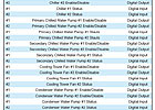
TABLE 2. Mission critical point allocatiion.
- Wiring ladder diagrams detailed adequately for field construction, including all related wiring. Ladder diagrams shall indicate terminal strip numbers, wiring logic for all control devices, safety interlocks, and motor control interface.
- Communications network schematic (LAN) indicating all user I/O devices and locations. Schematic shall include location of all BAS panels, controllers, and third-party devices provided by equipment manufacturers.
- Wiring diagrams and layouts for each control panel (show termination numbers).
- Floor plan schematic diagrams indicating field sensor and controller locations.
- For each physical point, provide a document (spreadsheet), which, at a minimum, should indicate the following:
- User point identification (ID) name
- Logical point name
- Alarmable (yes or no)
- Point description
- Point loop identification (P&ID)
- DDC panel ID
- Fail position (open or closed)
- Digital or analog
- Latched point (yes or no) and delay if latched point
- Analog range of device, if applicable
- Analog occupied setpoint
- Analog occupied high-limit alarm
- Analog occupied low-limit alarm
- Analog unoccupied setpoint
- For each virtual point, provide a document (spreadsheet) which, at a minimum, shall indicate the following:
- User point identification name
- Logical point name
- Control range, if applicable
- Point function and use
Conclusion
BAS have advanced to incorporate full building integration and control. Conventional building control systems are classified as DDC systems that are utilized to control HVAC equipment and monitor/alarm the building’s environmental conditions. The inherent difference in a mission critical BAS is that it enhances the abilities of a DDC system to incorporate a whole building approach to monitoring and control.A properly designed and specified BAS integrates information from all building components into one common system. The integrated information can then be utilized by the BAS to control HVAC systems in response to building events and provide facility management personnel an integrated means of troubleshooting during times of failure.ES
