Major changes at Office Building II were made, including replacing the existing chillers with two 350-ton centrifugal chillers and one 140-ton magnetic bearing centrifugal chiller.
The Washington State Capitol in Olympia, WA houses the State Legislature, as well as the offices of the governor, lieutenant governor, secretary of state, and treasurer. Unlike many other capitols around the country, Washington’s Capitol is not confined to one building. Instead, it consists of 36 buildings comprising more than 4 million sq ft - 350,000 sq ft of which was constructed before 1920.
Given the age of the buildings on campus, it became obvious in the late 1990s that many were in need of major rehabilitation. Aging and overburdened mechanical systems were failing, roofs and walls were leaking, utility spaces were jammed with cabling, electrical systems were overtaxed in an attempt to meet modern office needs, and the required fire protection and safety standards were not being met.
A major earthquake in 2001 exacerbated many of these problems, causing renovations to begin around the Capitol in earnest. Part of these renovations included taking a hard look at all the chilled water systems on campus. Several studies showed that more chilled water capacity was required and that the existing distribution system had some deficiencies, resulting in buildings not being able to utilize all the chilled water that was being produced.
Once the problems were mapped out and a budget approved, significant upgrades were made to the chilled water system, funded, for the most part, through utility savings and utility rebates: New chillers have been installed, controls have been optimized, and the distribution system has been stabilized. The retrofits will most likely continue well into the future, as more money becomes available to meet the growing cooling needs of Capitol occupants.
Powerful Upgrade
The first extensive chilled water project at the Capitol involved analyzing the entire chilled water distribution system throughout the campus. This entailed completely mapping the system from the point of generation to the point of consumption, which included more than a mile of underground chilled water piping.The detailed analysis showed that, in reality, the two older 680-ton chillers in the aptly named mechanical equipment building, the Power House, (a third absorption chiller had already been demolished) could provide enough cooling to the eight buildings on the chilled water loop. The central plant issue then became one of efficiency. The older machines were operating at approximately 1.9 kW/ton and experiencing increased annual maintenance costs to keep them online. It was time to infuse new, higher efficiency equipment. As a result, a 680-ton Carrier centrifugal chiller was installed as the lead chiller, with the two older chillers providing backup until there is money in the budget to replace them.
Deciding which chiller to install was a challenge, because the chosen vendor would be required to provide a chiller management system that could optimize the entire system. In addition, the manufacturer would have to assume responsibility for all the chilled water equipment, including the pumps, cooling towers, and remaining chillers, and sequence them in the most efficient manner.
According to Mike Dean, project director with McKinstry/Essention in Seattle, “Carrier gave us the best kW per ton value and the NPLV (nonstandard part load value) and the IPLV (integrated part load value) ratings were in the range that we had to have. Because this was a performance contract, we had to guarantee the efficiency of these systems when they were fully constructed and operational. Their numbers were appropriate, and they also had the right refrigerant type [R-134a].”
Before the new chiller could be installed, the power service had to first be upgraded. “The existing chillers at the Power House were 4,160-V chillers, and since the new Carrier chiller was a 480-V chiller, we had to upgrade the power service to put in a large enough transformer to feed the new chiller plus the additional chillers that will eventually take the place of the old 4,160-V chillers,” said Mark Nieman, P.E., CEM, a senior energy engineer with McKinstry/Essention.
The tower that had been serving the absorption chiller in the Power House had been mothballed. When it was brought back into service, new components had to be fabricated due to the fact that the tower manufacturer was no longer in business.
Changes Bring Challenges
Other changes made in the Power House include installing a more efficient and effective pumping system for the Carrier chiller; the pumps for the existing chillers were left in place. With the new system, it was possible to reduce the overall flow, especially on the condenser waterside to the cooling tower, which made a huge difference in the amount of energy consumed. VFDs were applied to all the chilled water pumps in each of the buildings.The three existing cooling towers were kept in place, but this resulted in new challenges. The tower that had been serving the absorption chiller had been mothballed when that chiller was demolished, so it had to be brought back into service (there were no funds available to replace it). Unfortunately, the manufacturer had gone out of business, and the spray heads and drift eliminators were no longer available; therefore, new components had to be fabricated in order to bring the tower back online.
Changes were also made to the various coupled and decoupled connections at each building along the chilled water loop. A decoupled arrangement was ultimately implemented, so the buildings could not directly impact the central loop, and the central loop could not directly impact the buildings. A pressure-independent DP flow-control valve assembly was installed at every building, which regulated the total amount of chilled water that was delivered to or consumed by each of those buildings.
“In the past, a larger building would come online, and it would actually draw the chilled water away from other buildings, so those buildings would be starved of chilled water,” said Dean. “With this approach, one building can only consume as much chilled water as it was designed to consume, and that helped stabilize the whole distribution system.”
Every chilled water coil was also examined. Three-way control valves were eliminated, and new two-way control valves were “right sized” for each application (which then dictated the size of the flow-control valve). The sequences of operation were rewritten for each AHU in order to take advantage of newer energy-efficient control strategies and in order to link the buildings to Carrier’s chiller automation system, which can also be accessed through the campus-wide “Metasys” system.
These programming changes allowed the existing air-handling systems to operate more efficiently. “The new system allowed us to reduce the total load on the chilled water system by programming in a purge mode, so if the temperatures are appropriate, the air-handling unit will turn on in the economizer cycle, and it will cool the building during the night,” said Dean.
The $1.3 million upgrade to the Power House was completed in 2004, and Nieman estimated the annual utility savings to be $37,400.
Other Changes On Campus
Once all the renovations were made to the Power House and the chilled water loop, attention turned to other cooling needs on campus. The Capitol campus is essentially split into two parts, and a main thoroughfare divides the two sections. The chilled water loop does not extend across the street, so the buildings on the other side of the road contain individual chillers, many of which are old and inefficient.The Transportation Building was in the most need, as it relied on two 36-year-old, R-11, 325-ton centrifugal chillers, which were sized based on traditional safety factors at the time. Once the building loads were actually logged (with dataloggers) and calculated, it was discovered that the two existing chillers could be replaced with two 250-ton, R-134a Carrier chillers.
The existing chillers were housed in the basement mechanical room, and removing them was no small task. “It’s a tight space down there,” said Dean. “We actually had to disconnect the main building ductwork to create a path to get the chillers out. There was no readily available access to the basement, so we fabricated an overhead crane system that would roll the equipment and chillers from the under-ground parking lot access door, and then lower them into the basement area. It wasn’t as easy as we had hoped.”
The secondary chilled water loop was converted from constant to variable flow, and new pumps and cooling towers were installed. A chemical-free Dolphin Water Treatment System from Clearwater Systems LLC, was also specified as a first-of-its-kind test case, which was definitely something new at the Capitol.
“It’s a non-chemical system,” said Nieman. “It’s a spool section that’s inserted in the pipe on the condenser water side, and it essentially shocks the biological components going through the water, making them inert. It reduces scale and biologicals, and you don’t use any chemicals in the process.”
The new $995,000 chilled water system was brought online in April of this year, and so far, the test results show that the Dolphin system is working well.

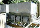
Getting access to the equipment in the basement of the Transportation Building was difficult. The building’s two 36-year-old, R-11, 325-ton centrifugal chillers were located in a very cramped basement mechanical room.
Office Building Overhaul
At the same time the chiller retrofits were taking place at the Transportation Building, major changes were also occurring at Office Building II. This building had two steam absorption units (527 tons and 376 tons) that provided cooling to the main part of the building, as well as a 180-ton chiller, which provided cooling to a dedicated area within the building.Due to several hundred thousand dollars in rebates (from other concurrent energy upgrade work) offered by the local utility, it was possible to remove the old steam units and right-side their replacements. The existing chillers were replaced with two 350-ton, R-134a Carrier centrifugal chillers, which would handle the main building load, and one 140-ton McQuay magnetic bearing centrifugal chiller, which would cool the process load-related space.
“We did a lot of research in qualifying the magnetic bearing chiller as a viable alternative,” said Dean. “We listed the pros and cons, and we decided to give it a try. When you get below a certain tonnage, centrifugal chillers are not economically viable or efficient, so it moves you into other technologies. The nice part is that Washington State is very progressive when it comes to trying new technologies.”
All three chillers came online in April of this year, and Dean noted that they have received numerous compliments on the low noise level of the McQuay chiller. In addition, it has provided a major improvement in energy efficiency over the unit that was previously there. The McQuay unit has its own controls, which interface with the Staefa BAS.
In addition to the new chillers, the 300,000-cfm air handler was significantly revamped. The built-up air handler dated to 1971, and the mixing damper section had started to break down. It’s a single system with VFDs on the fans that serve series fan-powered VAV boxes with hot water reheat coils in the building itself. The all-pneumatic dampers were standard blade-type units that were failing and not repairable.
“We replaced the entire mixing damper section, including the outside air and return air dampers. It’s very impressive to see a new large set of low-leakage dampers with electric actuators and DDC in this building,” said Nieman.
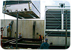
New pumps with VFDs were installed, and the entire primary piping was reconfigured and replaced. The existing forced draft centrifugal cooling towers were replaced with induced draft towers, which required the use of the largest crane on the West Coast to place them on the roof. The VFDs on the tower motors allow the chilled water plant controller to take advantage of the variable speed and the lower pressure drop of the induced draft towers.
The building’s underground parking garage ventilation system was also modified. CO sensors were installed, and the system was modified to use building relief air as the primary air source for the garage. “This essentially turns it into a heated garage because we’re using waste air as the primary air source,” said Nieman. “If the CO levels become unacceptable, there’s a back-up system that purges the garage with outside air.”
The new mechanical systems in Office Building II cost approximately $4.5 million, and local utilities offered $217,000 in rebates.
The changes won’t stop now, though, as other buildings around the campus are scheduled for new mechanical systems in the near future. Dean said he enjoys this type of work and looks forward to these other retrofits. “It gives you a real sense of accomplishment to go into an older existing facility and make these types of significant modifications that improve tenant comfort and reduce energy consumption at the same time.”

