
The energy intensity and utility costs associated with operating a commercial kitchen ventilation (CKV) system are well recognized within the HVAC design community. However, there is no piece of equipment that generates more controversy within the foodservice industry than the exhaust hood, in all its styles and makeup air combinations. From the onset of a commercial kitchen project, the design of the exhaust ventilation system is challenged by an inherent disconnect between the foodservice consultant and the mechanical engineer.1The capacities of exhaust hoods in commercial kitchens range considerably from 500 to 1,500 cfm in coffee shops and delis; from 1,000 to 5,000 cfm in quick service restaurants; from 4,000 to 12,000 cfm in casual and full-service operations; and from 10,000 to 30,000 cfm in large institutional kitchens.
All in all, there are three billion cfm being exhausted from commercial kitchens in the U.S. The conditioning of the outdoor air that is required to replace the air exhausted from the kitchen, along with the associated fan energy, imposes a significant energy burden - at least 50% of the total HVAC load in commercial foodservice facilities.

Figure
1. Styles of exhaust hoods.
Designing For Precise Flow
There is often an underlying supposition that the exhaust hood will function satisfactorily if it is specified in accordance with its UL-listed airflow capacity. This may be far from reality! Research over the past 10 years has demonstrated that hood type and local introduction of makeup air have a significant impact on exhaust and makeup air ventilation rates. Integrating the CKV system with the front-of-the-house HVAC system has the potential to lower the energy burden and improve kitchen comfort by maximizing the transfer of outdoor air supplied to the dining room as a contribution to the makeup air requirement. A related and appealing energy saving strategy is the application of demand ventilation control to kitchen exhaust systems.The replacement air required for commercial kitchen ventilation systems is always 100% of the exhaust air - what goes out must come in. A common design practice is to supply at least 80% of replacement air using an independent makeup air unit (MAU) with the remaining 20% supplied by conditioned outside air from HVAC units serving the kitchen or transfer air from adjacent spaces. This keeps the kitchen under a negative pressure (relative to the dining room) to prevent cooking odors from migrating into the dining area.
In many climates, the replacement air from an independent MAU is not conditioned, which may create uncomfortable conditions (too cold and/or too hot) in the kitchen. In other climates, the makeup air is heated, which in many cases results in simultaneous heating (by the MAU) and cooling (by the HVAC unit) of the kitchen during the shoulder seasons.
Conventional design practice does not take full advantage of the relatively high rate of occupancy ventilation air that is introduced into the dining room or other areas of the building adjacent to the kitchen. There is an opportunity to use this code-required (based on ASHRAE Standard 62) outdoor air supplied to the dining room as replacement air for the exhaust hood, thus reducing (or in some cases, even eliminating) the fraction of replacement air from the independent MAU. Since occupancy ventilation air is conditioned in most cases, transferring it to the kitchen as a contribution to the replacement air requirement can improve comfort conditions in the kitchen.
The following approach is recommended2for optimizing the design of a CKV system.Minimize the design exhaust ventilation rate.This involves appropriate selection of the type and style of exhaust hood for the line of cooking equipment. Accomplish this with prudent selection and application of UL-listed hoods and by considering the “exhaust flow” recommendations from hood suppliers for the cook line. Exhaust hood manufacturers’ engineering departments have a lot of knowledge that consulting engineers can tap to select an appropriate exhaust rate and enhance the specifications with details such as increasing overhang, minimizing the rear gap (between appliances and back wall), adding side panels, and using proximity-style hoods where appropriate. Incorporating demand ventilation controls falls within the scope of minimizing the exhaust ventilation rate and associated energy burden.
Integrate the CKV system with the building HVAC system. This design step is one that is easily skipped, since the specification of a dedicated makeup air system to replace 80% of the exhaust air ensures air balance and facilitates plan check. However, it does not facilitate system optimization (from either an energy efficiency or a kitchen comfort perspective). The goal is to utilize as much Standard 62 outdoor air from the dining room and other spaces as possible as a contribution to the replacement air requirement. Maximizing transfer air is the key to HVAC system integration. Not only can hood performance be superior, the kitchen environment will benefit from the cooling contribution of the “recycled” dining room air.
Minimize dedicated makeup air volume and velocity. This concept is counter to general practice, as locally supplied makeup air is often the easiest design solution. However, locally supplied makeup introduces air quantities and velocities that often interfere with the ability of the exhaust hood to capture and contain cooking effluent. Once the transfer airflow rate has been established, the quantity of dedicated makeup air is determined by subtracting the amount of transfer air from the total exhaust air volume. Introduce this reduced amount of makeup air at the lowest velocity possible by maximizing the area of the supply grilles. Do not specify four-way diffusers anywhere near exhaust hoods. Perforated plate diffusers are preferred.
Hood Specs
Let’s take a closer look at how hood specifications and makeup air introduction can affect the design exhaust rate and system performance.The hood factor – capture and containment (C&C). The design exhaust rate depends on the hood style and construction features, as well as factors mentioned above. Wall-mounted canopy hoods, island (single or double) canopy hoods, and proximity (backshelf, pass-over, or eyebrow) hoods all have different capture areas and are mounted at different heights and horizontal positions relative to the cooking equipment.
Generally, for a given line of appliances, a single-island ceiling-hung canopy hood will require significantly more exhaust than a wall-mounted canopy hood, and a wall-mounted canopy hood requires more exhaust than a well-engineered proximity (e.g., eyebrow-, backshelf- or pass-over-style) hood. The performance of a double-island ceiling-hung canopy hood tends to emulate the performance of two back-to-back wall-canopy hoods, although the lack of a physical barrier between the two hood sections makes this configuration more susceptible to cross drafts. Single-island canopy hoods present the “ultimate” capture and containment challenge in hood applications and are typically the foundation of the problems in display cooking kitchens.
Chapter 31, titled“Kitchen Ventilation” in the 2003 ASHRAE Handbook - Applications3provides a table of typical design rates for “listed” hoods. This table was developed with input from the major hood manufacturers in an effort to provide the design engineer with a sense of realistic airflow rates for a given hood application. The ranges reflected in this table are due to the fact that there are large variations in the cooking effluent challenge for different foodservice operations, even for the same “duty” category of appliances. It is also due to the fact that listed hoods are not created equal - some hoods work better than others. This is why it is important to select the design ventilation rate using hood manufacturers’ software tools or hood sizing formulas, rather than their “listed” values.
Side panels. Side panels or skirts (both partial or full) permit a reduced exhaust rate in most cases, as more of the replacement air is drawn across the front of the equipment, improving capture of the effluent plume generated by the hot equipment. They also mitigate the negative effect of cross drafts. Side panels are a relatively inexpensive way of improving hood performance. It is important to know that partial side panels can provide almost the same benefit as full panels. Laboratory testing has demonstrated reductions in capture and containment airflow rates up to 100 cfm/ft of hood by the application of partial side panels on 10-ft wall-canopy hoods.4 Although defying its definition as an “island” canopy, end panels can dramatically improve the performance of a double-island or single-island canopy hood.
Makeup air factor. Introducing makeup air into the kitchen without disrupting the ability of the hood to capture and/or without causing discomfort for the kitchen staff is a huge challenge. Dumping 8,000 cfm of makeup air, for example, along the front of a 25-ft cook line does not go as smoothly in practice as it appears on a theoretical air balance schedule. Another way of looking at this is to never “force” air toward the hood - make the hood do the work and “pull” the air toward itself. Not only can high makeup air velocities hamper the ability of the hood to capture and contain cooking effluent, locally supplied makeup air that is too cold or too hot can create an uncomfortable working environment.
Makeup air that is supplied through displacement ventilation (DV) diffusers remote from the hood, perforated diffusers located in or near the ceiling, or as transfer air from the dining room, generally works best if air velocities approaching the hood are less than 75 fpm. Makeup air introduced in close proximity to an exhaust hood, however, has the potential to interfere with the hood’s ability to capture and contain due to higher velocities. The chances of makeup air affecting hood performance increases as the percentage of the locally supplied makeup air (relative to the total exhaust) is increased. In fact, the 80% rule of thumb for sizing airflow through an MAU can be a recipe for trouble, particularly if the exhaust capacity has been oversized.
Demand ventilation controls. The concept of demand controlled ventilation is attractive within the design of commercial kitchens. While this technology currently is led by one manufacturer, it is anticipated that other strategies of demand control will emerge and that its specification in commercial kitchens will become mainstream. A primary component of DV control is a VFD on both the exhaust and makeup air fans. Integrated with a sensing system to modulate the exhaust flow in response to the heat and smoke being produced by the cooking equipment, DV can yield substantial energy savings. Furthermore, it allows the engineer to incorporate a larger cfm safety factor within the exhaust hood specification without an ongoing energy consumption penalty to the foodservice operator. This safety factor can be “commissioned out” of the system, but it is always there if needed (a good choice for an island canopy hood, as replacing the exhaust fan is not the preferred option when the hood fails to perform). The economic return on a DV control package generally increases with the size of the project (larger exhaust systems in hospitals, hotels, and casinos).
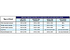
Table 1. Typical exhaust rates for “listed” hoods. Source: 2003
ASHRAE Handbook - Applications, Chapter 31, “Kitchen Ventilation.”
Bottom Line
Hold “spec” on the design exhaust rate - it should not be negotiable within the competitive bid or during evaluation of alternative ventilation system proposals based on a lower UL-listed cfm value. Do not use short-circuit hoods with internal makeup air supply.Commission the CKV system – air balancing of all exhaust and makeup air, and performance testing of CKV systems must be included in all jobs, as these actions are required by most codes, and it “closes the loop” to ensure that all aspects of the system are functioning as designed.
The science of commercial kitchen ventilation continues to evolve at a rapid pace, driven by ASHRAE research projects, an expanding line of innovative products, and research at the Commercial Kitchen Ventilation Laboratory in Wood Dale, IL. All of this information, along with the results of a California Energy Commission-funded makeup air research project, are leading to updates of the national codes (NFPA 96 and IMC) and fundamentally changing the way CKV systems are designed and operated.ES
Sidebar: Avoid the Short Circuit
Internal makeup air hoods (short circuit) were developed as a strategy to reduce the amount of conditioned air required by an exhaust system to meet code requirements by introducing a portion of untempered makeup air directly into the exhaust hood reservoir.However, laboratory testing and field experience have clearly demonstrated that when short circuit hoods are operated with significant percentages of internal makeup air, they fail to capture and contain the cooking effluent.5 Dilution of the cooking effluent with the internally supplied MAU may make it difficult to visualize spillage, but a degraded kitchen environment is confirmation that hood performance has been compromised. Fortunately, the specification of short-circuit hoods has decreased over the past few years as there are more effective strategies for reducing the energy burden of a CKV system while maintaining an acceptable kitchen environment.
Simply stated, short-circuit hoods are not recommended under any circumstances! This recommendation is endorsed by leading hood manufacturers, even though they may still include short-circuit hoods in their catalog and competitively bid a project based on a short-circuit hood spec. In other cases, the local representative may promote the concept in pursuit of a marketing advantage and the consultant’s specification on a project.


