A financial firm located in this Boston building wanted its new server area to remain locked and sealed even while the CRAC units were being serviced. Working within the constraints provided by the firm, an engineering firm and CFD expert repositioned the servers to properly even out the heat load throughout the room.
When a financial services company sought to identify potential problems in its new data center room prior to construction, it turned to Facilities Engineering Associates (FEA). FEA felt that computer simulation would address the unique nature of the cooling problems in this application.
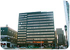
The financial firm is located in an 860,000-sq-ft building called 245 Summer St. in Boston's Financial District. FEA designed the data center with Liebert computer room air conditioner (CRAC) units in mechanical rooms on either side of the server area. This approach made it possible to keep the server area locked and sealed even while the CRAC units are being serviced. FEA's Bill Flaherty said Fluent Incorporated was selected as a consultant to perform the analysis because of the company's experience in addressing HVAC applications.
THE ORIGINAL DESIGN
The room was originally designed so that cold air would flow out of the CRAC units, under the raised floor, and up through perforated tiles into the server area, forming cold aisles between racks of servers. The cold air would then be drawn into the air intakes of the server racks, where it would take on heat from the equipment. The hot air would then exit from the backs of the servers into hot aisles, where it would be drawn up to the ceiling and through perforated panels for return to the CRACs.Kishor Khankari, the Fluent consultant assigned to the project, began by modeling the geometry of the two proposed proof-of-concept designs using Airpak computational fluid dynamics (CFD) software. In one proposed layout, the CRAC units are parallel to the server racks, and in the other design they are perpendicular.
The simulation results provided the air velocities, pressures, and temperatures throughout the server room and lower plenum, and were used to illustrate the resulting airflow patterns for each layout. The global airflow patterns showed that the design worked as intended, with the air rising through the perforated sections of the floor, flowing through the racks, and exiting through the returns in the ceiling.
UNDER CLOSER EXAMINATION ...
"While the design seemed to be working well at first glance, closer examination showed several serious problems," said Fran Escott of FEA. Cooling air is drawn into the cold aisle between the high-density rack and the adjacent low-density rack through the perforated floor tiles. Following the temperature-coded pathlines, it was determined that the hot air exiting from the high-density rack circled over the top of the rack and re-entered the cold aisle, where it was drawn into the upper intake portion of the neighboring low-density rack.The lower portion of the low-density rack was not affected. It continued to be properly cooled by air entering through the floor tiles. Temperature contours on the rack intakes further illustrated the problem. A similar problem occurred for the parallel orientation case, where the high-density rack was positioned between two normal-density racks. Hot air exiting from the high-density rack circled above and around the sides of the rack and re-entered the cold aisle, compromising the cooling air that was delivered through the floor.
"The proof-of-concept simulations demonstrated that the root cause of the problem was with the layout of the high-density racks," said Leo Soucy with FEA. "It was apparent that the original design concentrated the high-load racks in a single row, which created a hot spot in that area." Working within the constraints provided by the client, FEA and Fluent engineers repositioned the servers to even out the heat load throughout the room.
DIFFERING HEAT LOADS
The engineers also addressed the fact that the heat load of the different racks varies widely, from 1 to 7 kW. The original model used the power ratings provided by the blade manufacturers, but the engineers recognized that deviations from the rated values could greatly affect the accuracy of the simulations. They therefore measured the power draw of each unit and discovered that the actual values were considerably less than the rated ones.Using this information, along with information from the simulations, the engineers were able to determine the A/C capacity required to cool the room. The calculation was based on the requirement that the failure of any single CRAC unit would not cause temperatures to rise to dangerous levels. Finally, they examined the predicted pressure losses throughout the room and lower plenum to determine the requirements of the fans used to drive the system. All of this work paved the way for the proper data center room design, and the financial firm is pleased with its results.
