
At the Lanterman Development Center, a chilled water system, rather than an ice storage system, was chosen because of space constraints.
The Lanterman Developmental Center in Pomona, CA, is one of four facilities in the State of California that helps and houses people who have developmental disabilities. The facility is home to around 530 developmentally disabled patients. Until just a few years ago, it was difficult to keep in-patients comfortable, as the facility's 30-year-old chillers were well past their useful lives. With no money in the budget to replace them, keeping the chillers operational was the primary concern, not energy efficiency.
Fortunately, the California legislature passed a bill that called for the upgrading of all four developmental centers in California, so the antiquated equipment at Lanterman could finally be replaced. It was decided that a major overhaul was required, which involved gutting the existing chiller plant and replacing all chilled water piping, leveling the cooling towers, and installing an above-grade stratified chilled water TES tank.
The new mechanical systems ensured that patients would be comfortable, while engineering and administrative staff at Lanterman could see comfortable energy savings in the area of $500,000 a year.
FIGURE 1. Constant and variable-speed operation curves for centrifugal fans, pumps, and compressors.
TEAM EFFORT
Designing the new mechanical systems for Lanterman involved an engineering team approach. Benjamin Sun, LEED® AP and vice president with Flack + Kurtz, San Francisco, was the team's lead engineer; Thomas Hartman, P. E. of The Hartman Company, Georgetown, TX, designed the controls; and John Andrepont, of The Cool Solutions Company, Lisle, IL, provided TES consulting support.All three parties decided from the start that they were going to collaborate on the Lanterman project. A D-B proposal was submitted to the California Department of General Services, and the team's engineering approach won the competition. Construction began in 2002, and the final punchlist was completed in 2003.
The TES system was part of the desired equatio early on, primarily due to a visit the Lanterman staff took to nearby California State Polytechnic University (Cal Poly). "We invited some of the decisionmakers from Sacramento down here to take a tour of Cal Poly's new chiller plant and TES system," said Art Parks, assistant chief of plant operations for the Lanterman Developmental Center. "The chief engineer gave a very impressive presentation and said that they had originally anticipated a 10-year payback on their system. Instead, their experience was proving that they would realize the payback in between five and seven years."
Given California's spiraling electricity rates, it made sense to install energy-saving TES systems at the developmental center. At Lanterman, three chillers ran all day on peak electricity rates during hot weather, while a fourth chiller was on reserve. The TES system would mean the facility could run its chillers at night, taking advantage of off-peak electricity charges, then distribute the chilled water from the TES tank during the day.
A chilled water system, rather than an ice storage system, made the most sense, mainly due to the space available for the equipment. "Lanterman is an open campus, and there were lands available around the central plant for the thermal storage tank," said Sun. "Ice systems are often used when there are space constraints. Also, chilled water systems are not as complex as ice systems."
In addition, Andrepont added, "When space is available and TES capacity is a few thousand ton-hours or more, chilled water TES generally has a first cost advantage vs. ice TES."
The TES tank installed at Lanterman is a CB&I above-grade welded-steel tank with a capacity of 10,700 ton-hrs in the current chilled water service, with supply and return temperatures of 40°F and 56°, respectively. "The tank is also designed for potential future conversion to ‘So-Cool' low-temperature fluid service, which would result in supply and return temperatures of 30° and 54°, respectively, and an associated increased TES capacity of 16,000 ton-hrs," said Andrepont.
FIGURE 2. The chiller plant energy use spectrum.
There are other considerations that need to be taken into account when designing and installing a TES system. According to Sun, it is important to check the elevations of both the facility and the storage tank. That's because if mechanical equipment located on the roof of the facility is higher than the top of the tank, water can drain back to the tank and overflow the TES tank, unless appropriate steps are taken in the TES-to-system interface, which Andrepont indicated were accomplished in this case.
Another important factor is the geotechnical survey, which will determine the soil conditions where the TES tank will be placed. The survey at Lanterman showed that additional support would be needed. "The contractor had to actually drive piles underneath it for the tank's foundation," said Sun. "Those tanks are fairly heavy, so how they get supported and where they get supported is very important."

New piping was installed in the Lanterman Center as well as a BAS with specialized control techniques. The plant now operates on demand-based control which features a simple control configuration.
KEEPING CONTROL
The TES system wasn't the only new equipment installed at Lanterman. The existing chiller plant was gutted, its four existing chillers were removed, and all the chilled water piping was replaced. "Everything was taken out," noted Parks. "Even the pedestals that the chillers had been sitting on were jackhammered out. The cooling towers were also demolished down to the earth. That was very stressful to me, because there was no going back."Rental chillers were brought in to keep Lanterman cool until the three new 600-ton Trane chillers could be installed along with three new Evapco cooling towers. The existing chilled water piping within the plant was inadequately sized for the new chillers, so it was removed and replaced with new piping.
Prior to the renovation, the chiller plant control was completely manual, so building automation became a large part of the retrofit equation. In addition, Hartman brought his own specialized control techniques into the project, which some may view as a radical departure from traditional methods.
"One of the technologies that we work with is a regimen for employing all variable-speed control of chilled water plants," said Hartman. "It's significantly more efficient than what can be achieved with conventional controls."
These technologies are based on Hartman's principle of operation, which is called the "equal marginal performance principle." This principle states that the operation of a system composed of multiple modulating components is optimized when the marginal system output divided by marginal system input is the same for all components.

FIGURE 3. An energy cost comparison of optimized all-variable-speed chiller plants.
"Basically what this means is that we're not operating the plant by setpoint control," said Hartman. "For example, in a typical plant, there is a leaving tower water temperature setpoint, and the tower fan is operated accordingly. We're not doing that here. We're using power-based relationships, which are a much more optimal way to operate the plant. And we're sequencing equipment based on optimal relationships, which is called the natural curve method of sequencing."

FIGURE 4. Annual energy savings of options.
CONTROL CONCERNS
Sun was initially apprehensive as to whether this control strategy could work with a TES system, because chillers normally need to run at full speed in order to charge the storage tank. Hartman countered that thermal storage is ideal for an all-variable-speed plant, because it would be possible to set the load wherever needed for optimal plant operation and the hours could be adjusted in order to charge the tank at maximum plant efficiency."Clearly, there will be times in very hot weather where the plant might be fully discharged, and there is not much time to recharge it, so the chillers will have to run flat out," said Hartman. "However, during 90% of the rest of the year, it is possible to use this method, and that's how we get such enormous energy savings."
He's not kidding when he talks about enormous energy savings. With this new technology, Harman tells plant operators that it will be possible to generate and distribute chilled water at an annual average efficiency of 0.5 kW/ ton, which is approximately half that of a traditional chiller plant.
It's important to note that Hartman's estimate of 0.5 kW/ton is not just for the chillers, but for the entire plant, including the condenser water pumps, cooling towers, chilled water distribution pump, etc. "A lot of engineers call those parasitic loads, which is a complete misnomer," said Sun. "If you take those ‘parasites' away, the plant doesn't actually work, because you can't just run the chiller."
Sun added that the measuring stick that the chiller manufacturers have used for many years is 0.5 kW/ton for the chiller only. Based on Hartman's control technique, the entire Lanterman chiller plant is running at 0.5 kW or less; in fact, some of the time, it can be down in the range of 0.3 kW/ton.
So if chillers have a nominal efficiency of 0.5 or 0.6 kW/ton, how is it possible to run an entire plant at a lower kW/ton than the nominal efficiency of the chillers? Hartman gladly answered that it's because at variable speed at part loads, the efficiency improves.
"With thermal storage, we carefully regulate it, so it's operating down at part load, at which point everything operates more efficiently if it's variable speed. Everything in this plant is variable speed, and we're using power relationships to control the equipment rather than temperature and pressure setpoints. It's a very effective method of operation," said Harman.
Besides using an entirely different strategy for operating the chiller plant equipment, Hartman tried, as much as possible, to incorporate everything on a network rather than using discrete points. "Since the plant is all variable speed, every motor in the plant has a variable-speed drive on it. Rather than connecting discretely, point by point, to turn the motor on and off and adjust the speed with different inputs and outputs, we just have a network connection to each one of those variable speed drives," said Hartman.
A conventional DDC system from Delta Controls, Inc. controls the chiller plant, and the VSDs have a BACnet interface.
Essentially the VSDs sit on the Delta Controls network and communicate directly with the control system. "This enables the Delta Controls system to look at a lot more information than you would have with a traditional hardwire or point-to-point type of wire configuration," added Sun.
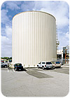
The TES tank at the Lanterman Center is an above-grade, welded-steel tank with a capacity of 10,700 ton-hrs.
The TES system at Lanterman is fully automated, so an operator does not need to remember to turn the system on and off - something that happens far too often at many facilities and results in wasted energy, noted Harman. At Lanterman, the operator sets up the schedule for charging the TES tank and when it needs to discharge. From there, the plant operates entirely automatically.
Hartman and Sun freely admit that one of the more challenging aspects of the Lanterman project was getting people to accept a completely new way of operating a chiller plant. Thanks to numerous meetings and discussions that occurred during the construction process, the programmers and the controls company became very familiar with the exact sequences, allowing for a smooth installation.
Even though it took awhile for plant personnel to become familiar with the new equipment and control sequences, no one can complain about the results. Parks noted that the new mechanical systems at Lanterman have been exceeding expectations from both a financial and a comfort standpoint.
"I have no complaints. From July 2004 to June 2005 our electricity bill was around $1.3 million, which represents a savings of roughly a half million dollars," said Parks. "In addition, before we got the new system we used to be bombarded by complaints. If there are any complaints now, our engineers resolve them, and managers at higher levels are no longer involved."

