Click for larger image
- Refer to this month's "HVACR Designer Tips" for project closeout, as well as the "Application Checklist" for scoring the system.
- When designing an energy conservation system, it is important to be able to collect the operating data so that actual ROI can be monitored and measured against the estimated ROI. The design engineer needs to work closely with the facility engineer to determine what metering and control components are required in order for the facility engineer to do his job efficiently. The same can be said for specifying the expansion of an existing CMMS system so that planned maintenance workorders are available on day one of occupancy.
- If energy simulation software is used for determining the optimum system selection and/or for life cycle analysis, this month-by-month energy consumption data should be forwarded to the facility manager to be used to benchmark trending data during the warranty phase of the project. This simulation exercise can be used to confirm and obtain two to eight LEED® credit points based on computer output.
- Integral to the long-term success of a building system is the initial commissioning process, followed by proactive building management. The cornerstone to this aggressive business plan is to facilitate a CMMS-ready system beginning in the design phase.
- Optimizing building automation capabilities is seldom achieved by most facilities. Instead, energy management is more often a reactive and sometimes manual task involving turning equipment on and off based on limited data collected.
- Like any quality process, data collection and data analysis are the foundation of peak facility management as it relates to energy consump-tion, operating cost, and maximization of useful equipment service life. BAS trending, through the use of graph presentations, can be invaluable to the facility management striving to educate others who need to know what operation and maintenance is responsible for. A picture is worth a 1,000 words. A BAS computer graph can be worth even more.
- Trending equipment performance, environmental performance, energy consumption, and system performance can be an integral part of LEED certification for new construction (the additional commissioning point), as well as an integral part of this certification for existing facilities.
Design Phase
- In addressing energy management capabilities in the design phase, standard office specifications need to be enhanced to reflect today's business tools. The design engineer needs to work closely with the facility engineer to determine what metering and control components are required for the facility engineer to efficiently and effectively do her job. The same can be said for specifying the expansion of an existing CMMS system or specifying the extension of the facility manager's existing CMMS system so that planned maintenance workorders are available on day one of occupancy.
- If energy simulation software is used for documenting the dual-fan, double-duct system performance, this month-by-month energy consumption should be used to benchmark trending data during the warranty phase of the project. This simulation exercise can also be used to obtain two to eight LEED credit points based on computer output.
Commissioning, TAB Closeout, and Warranty Phase
- Verification of software programming needs to be reviewed by the commissioning firm and the facility manager to understand the methodology that went into establishing the formulas and programming associated with energy management and system trending.
- When commissioning the computer software programs, it is important that the commissioning firm have access to the flow diagram (control logic) as part of the FPT procedures.
- When commissioning/observing terminal equipment performance, it is recommended that only a small percentage of (e.g., 15% or 20%) of this equipment be commissioned when the terminal devices reach a quantity of 50 devices or more. The intent is to minimize commis-sioning cost by randomly selecting the number of double-duct and VAV terminals, placing the burden of proof of satisfactory performance on the contractor for all the terminal equipment.
- If 100% of the randomly checked terminal equipment commissioning passes, it can be assumed that the other terminal equipment will also pass. If there is failure of one or more air terminals, the contractor will need to address this deficiency before demonstrating another 15% of the equipment at a cost to the contractor for the additional commissioning services.
- The commissioning team for this month's application should include the commissioning firm, the owner's project manager and BAS computer engineer, the BAS contractor (which may include AHU-1 equipment computer engineers), and the mechanical trade contractor.
- When observing the BAS computer FPT, the commissioning firm will need to have a commissioning engineer at the computer and another commissioning engineer or technician at the end devices to observe "action/reaction."
Trending Setpoints
- Space temperature: Drybulb, wetbulb, and outdoor air temperature.
- Energy shall be in Btuh converted from kWh, cfm, and temperature rise.
- Predictive maintenance run-hrs at 4,380 hrs for motors and in alarm at 5,000 hrs.
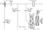
- Predictive maintenance static pressure resistance will be at 0.7-in. pressure drop across DP-1C transmitter serving SAFC-1 filter, and DP-1H transmitter serving SAFH-1 filter and in alarm will be at 0.9-in. pressure drop at DP transmitter.
1. BAS COMPUTER TRENDING SPACE TEMPERATURE
ACTION: BAS computer shall trend space temperature to collect and establish historical data profile to improve supply air discharge temperature control based on outdoor air temperature. The REACTION shall be:- Outdoor air temperature transmitter OATT-1 is signaling (drybulb, dry and wetbulb, humidity) temperature.
- Space air temperature transmitter T-1 is signaling (drybulb, dry and wetbulb, humidity) temperature.
- Space air temperature transmitter T-2 is signaling (drybulb, dry and wetbulb, humidity) temperature.
- Space air temperature transmitter T-3 is signaling (drybulb, dry and wetbulb, humidity) temperature.
- Discharge air temperature transmitter TT-1C is signaling (drybulb, dry and wetbulb, humidity) temperature.
- Discharge air temperature transmitter TT-1H is signaling (drybulb, dry and wetbulb, humidity) temperature.
2. PREDICTIVE MAINTENANCE PROGRAM FOR ISSUING A WORKORDER FOR AHU-1 UNIT
ACTION: BAS computer shall inventory run-times for AHU-1 fan motors to issue PM workorder per unit based on motor online signal. The REACTION shall be:- 4, 380 run-hrs for SAFC-1 results in (workorder, no workorder, alarm at computer).
- 5,180 run-hrs for SAFC-1 results in (workorder, no workorder, alarm at computer).
- 4,380 run-hrs for SAFH-1 results in (workorder, no workorder, alarm at computer).
- 5,180 run-hrs for RAF-1 results in (workorder, no workorder, alarm at computer).
- 4,380 run-hrs for PF-1C filter results in (workorder, no workorder, alarm at computer).
- 4,380 run-hrs for PF-1H results in (workorder, no workorder, alarm at computer).
3. PREDICTIVE MAINTENANCE PROGRAM FOR ISSUING A WORKORDER FOR AHU-1 UNIT
ACTION: BAS computer shall monitor static pressure across AHU-1 filters to issue PM workorder per unit based on resistance across filter. The REACTION shall be:- 0.25 pressure drop at DP-1H results in (workorder, no workorder, alarm at computer) to change filter.
- 0.95 pressure drop at DP-1H results in (workorder, no workorder, alarm at computer) forecasting upcoming request to change filter.
- 0.7 pressure drop at DP-1H results in (workorder, no workorder, alarm at computer) to change filter.
4. TOTAL ENERGY CONSUMPTION BENCHMARKING
ACTION: BAS computer will be programmed to compare total actual energy consumption to simulated energy consumption forecasted in the design phase. The REACTION shall be:- Forecasted energy simulation shall be (heat loss and heat gain, life cycle, static regain) computer program.
- Actual energy consumption shall be (simulated, measured, forecasted) BAS computer program output.
- MBtuh is (Btuh/1,000, Btuh plus kWh/1,000, maximum building hours).
- Degree days are (degrees above 75°F and below 65°F, degrees above and below 65°F, degrees above and below 60°F) outdoor temperature.
- Actual energy consumption shall be compared to (historical data, life cycle data, FMS and VSD data) software program.
5. HOURLY ENERGY CONSUMPTION BENCHMARKING
ACTION: BAS computer will be programmed to compare actual AHU-1 energy consumption. The REACTION shall be:- FMS-1C with TT-1 and TT-2 input can provide (total, cold supply, return) energy consumption.
- VSD energy input can provide AHU-1 (hp, Btuh, kW) to add to total energy consumption.
- Total energy consumption shall be in (cfm, DT, MBtuh)/sq ft/hr.
6. MONITOR RUN-HRS AHU-1 UNIT FANS
ACTION: The BAS computer shall continuously monitor the number of run-hrs of SAFC-1, SAFH-1, and RAF-1 operate. The REACTION shall be:- BAS computer shall sum AHU-1 run-hrs from (VSD-1C, 1H, and RA; FMS-C, H, and R; both VSD and FMS) signals.
- Individual fans shall sum kWh from each (VSD, FMS, TT-1C and 1H) signal.
- BAS computer shall graph total (days, hrs, min) of the three different systems.
Test 208 LABORATORY AND OFFICE SPACE SERVED BY A DUAL-FAN, DOUBLE-DUCT SYSTEM, BASIC SYSTEM - DESIGN TEST
ANSWERS:
1) dry and wetbulb; drybulb; drybulb; drybulb; drybulb; drybulb; temperatures;
2) workorder; alarm at computer; workorder; alarm at compuer; no workorder; no workorder;
3) no workorder; alarm at com-puter; workorder;
4) life cycle; measured; degrees above and below 65°F; life cycle data;
5) cold supply; Btuh; MBtuh;
6) VSD-1, 1H, and RA; VSD; hrs.
